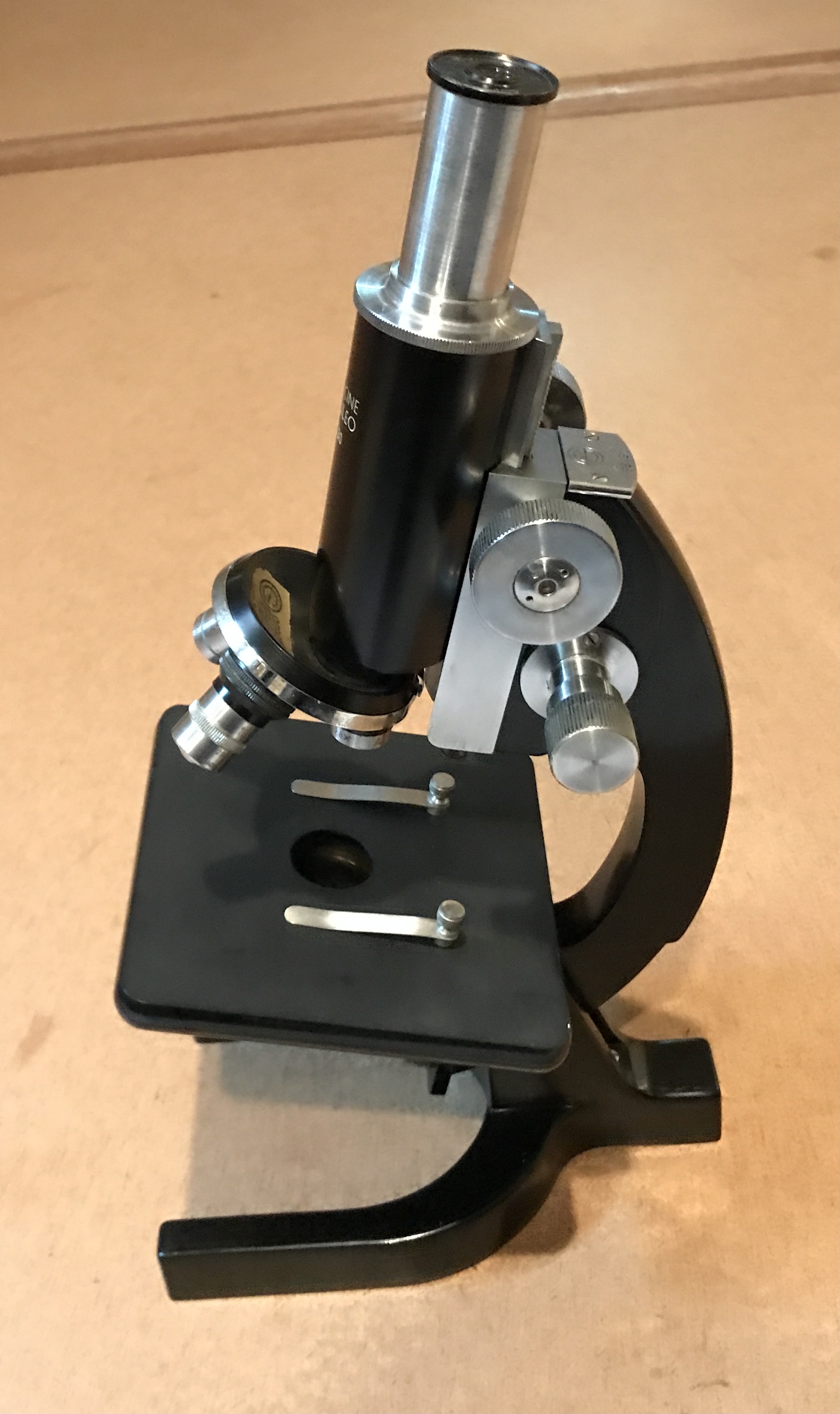
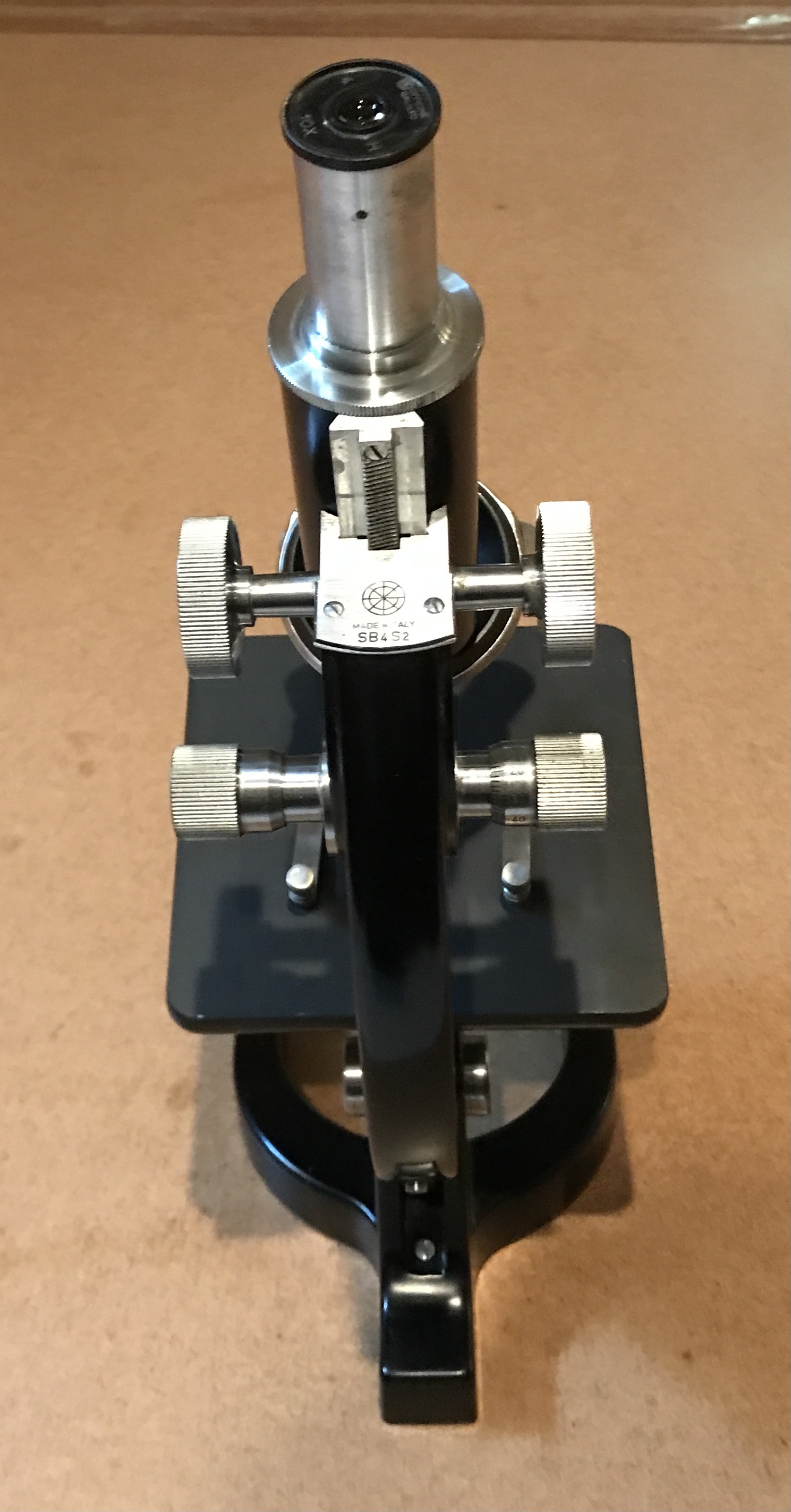
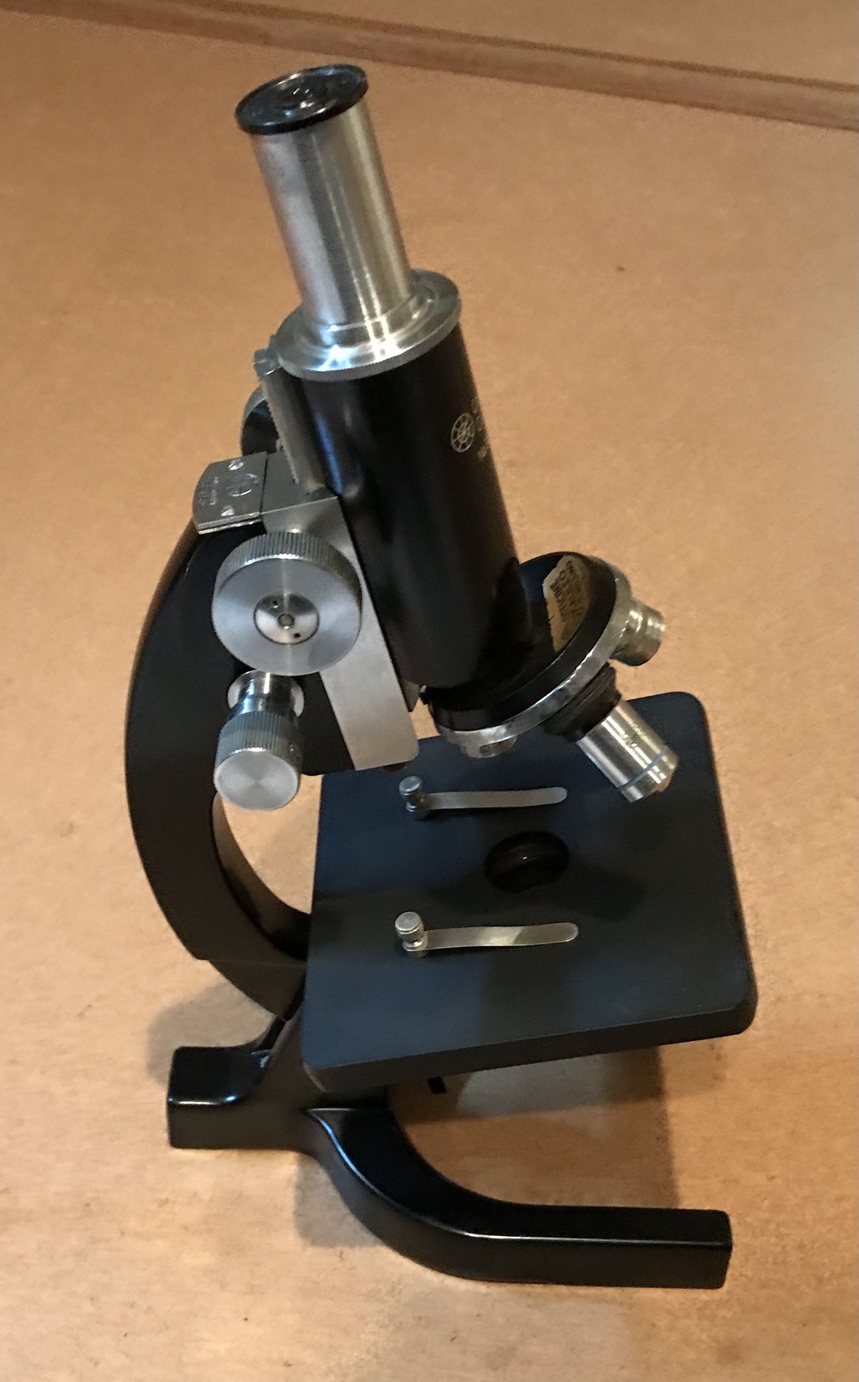
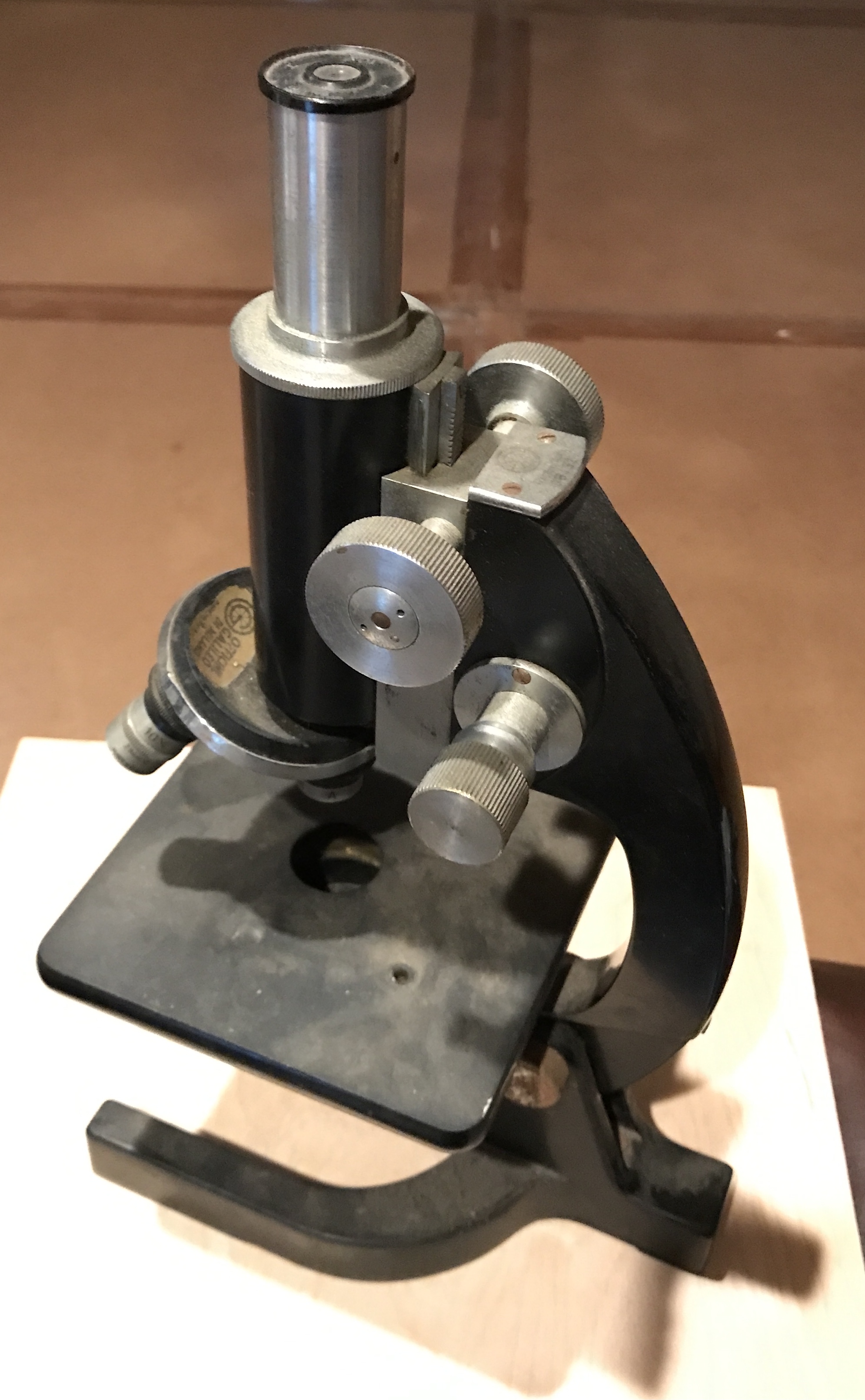
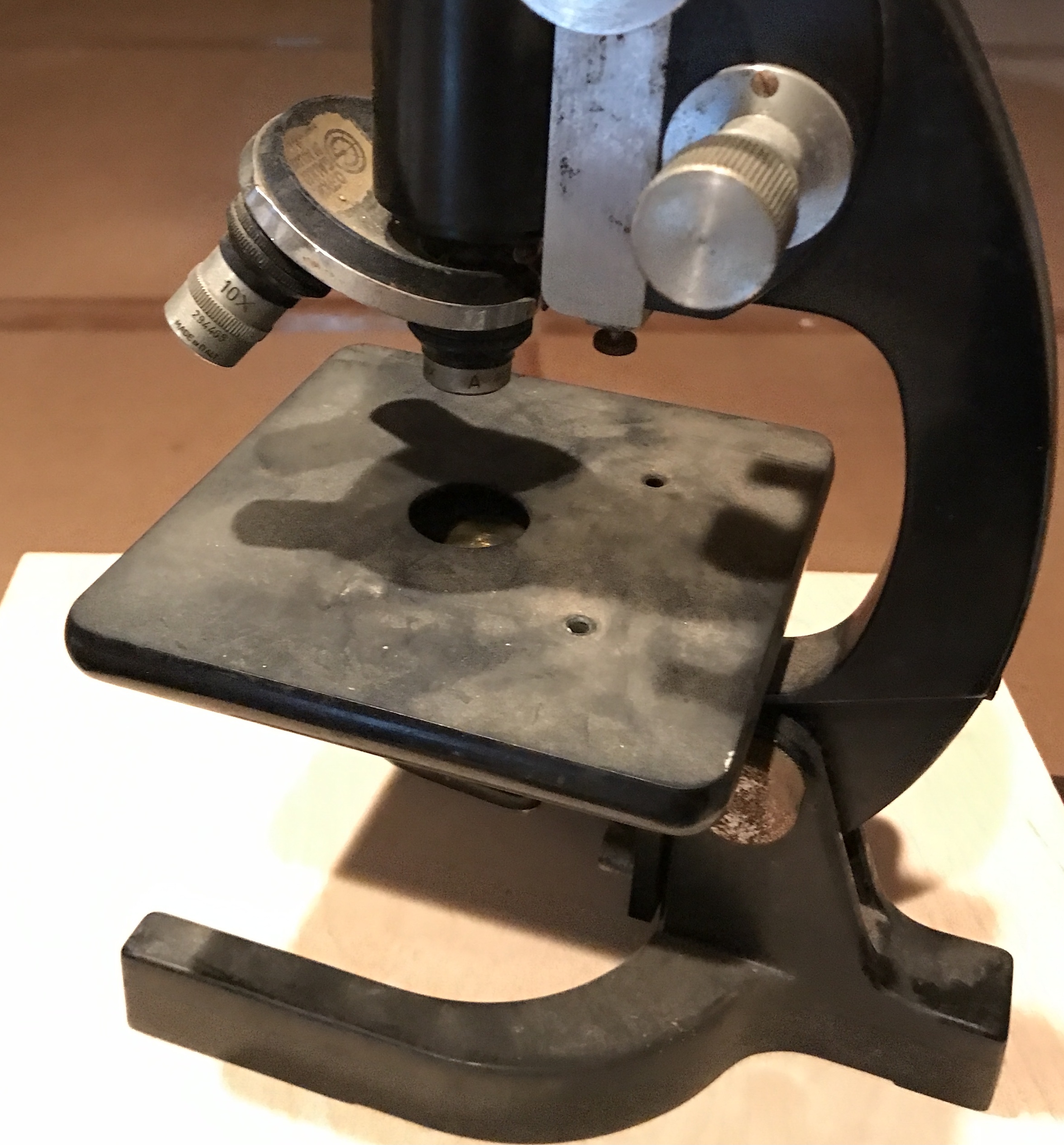
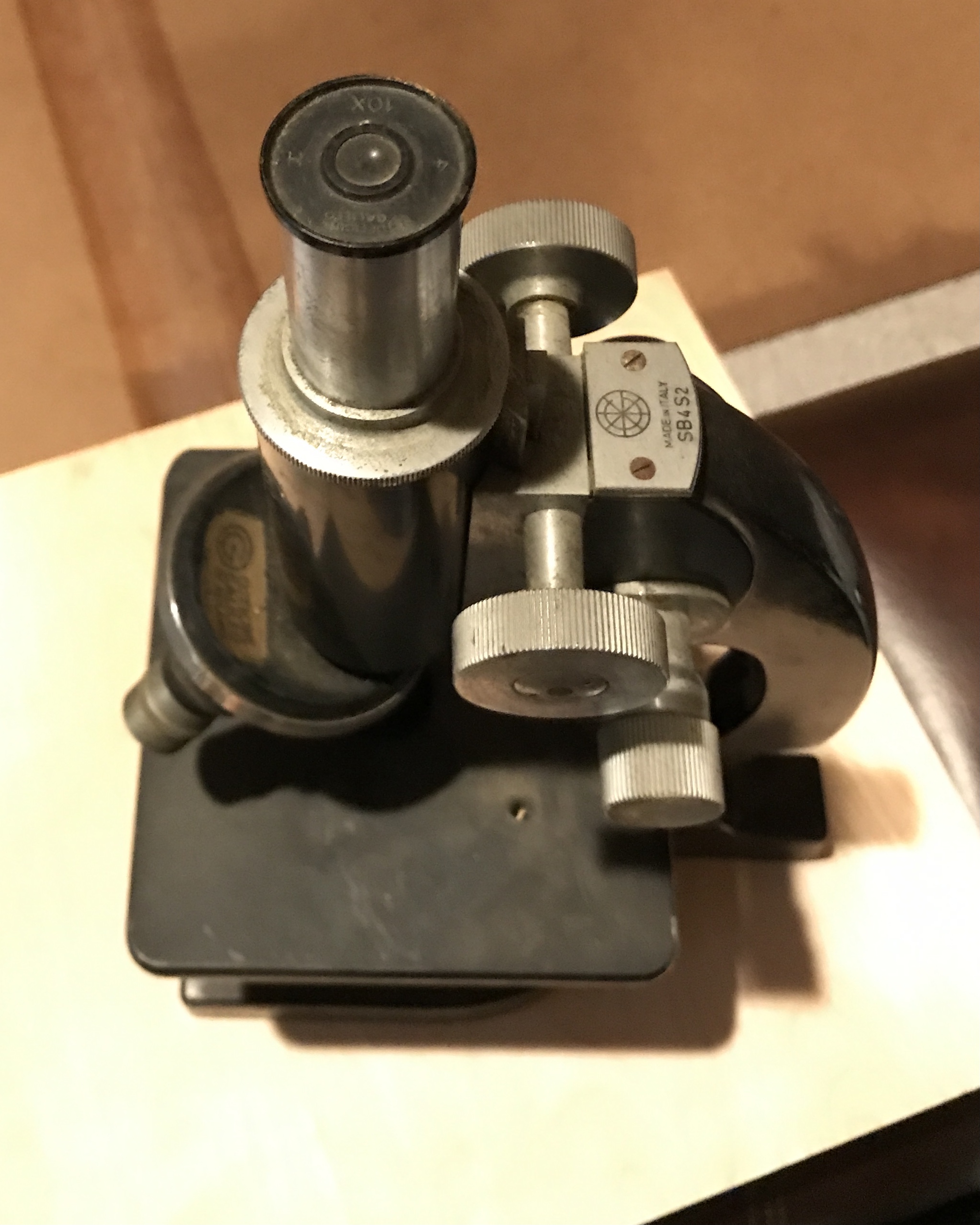
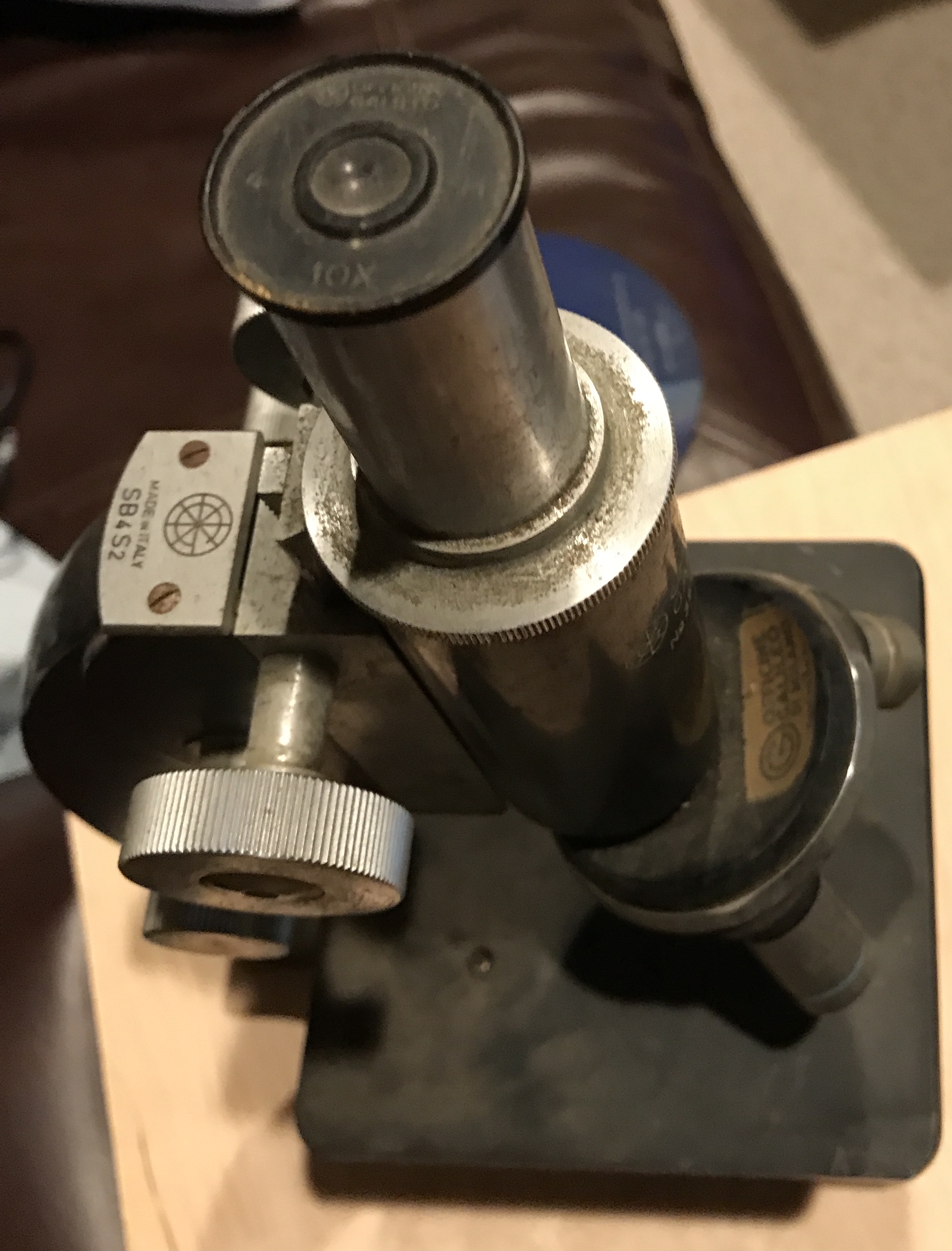
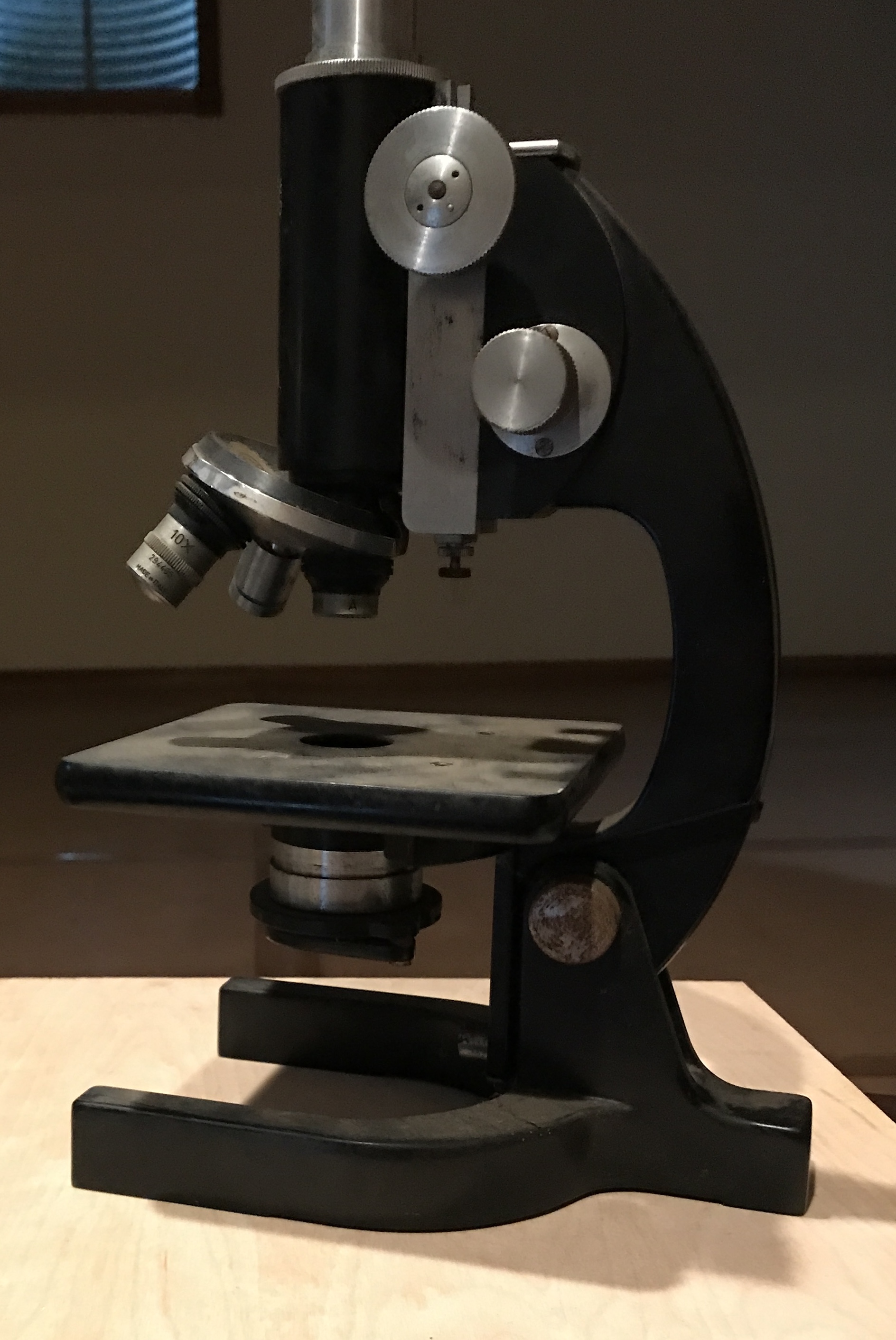
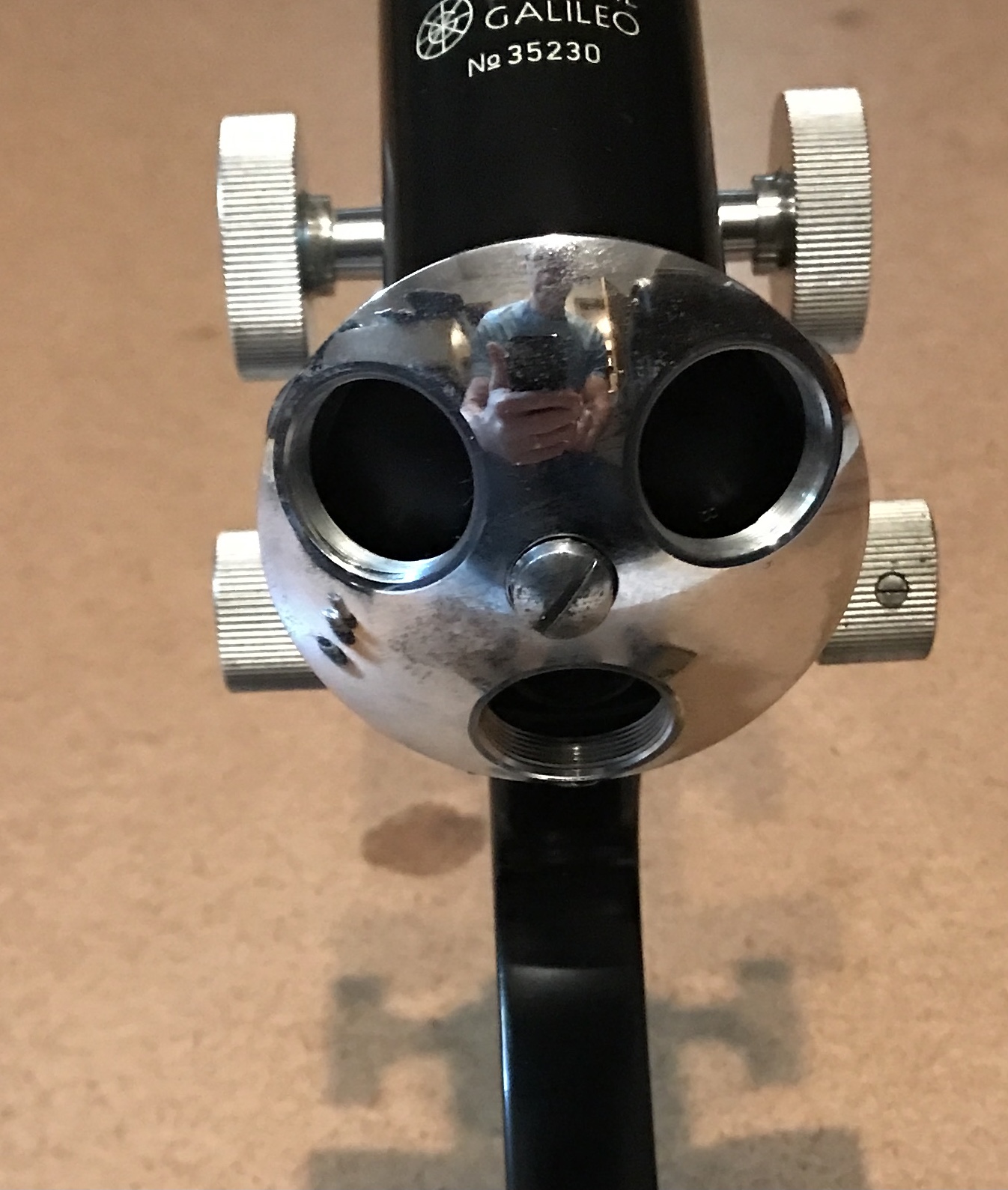
I purchased an old professional microscope for $20 at the Tri-State Antique Market in Lawrenceburg at the beginning of the month. It is time to restore it. The initial documentation of this restoration will mostly consist of pictures. The biggest challenge will be keeping all of the parts in some sort of order. The first four photos show the dirty microscope in all its glory.
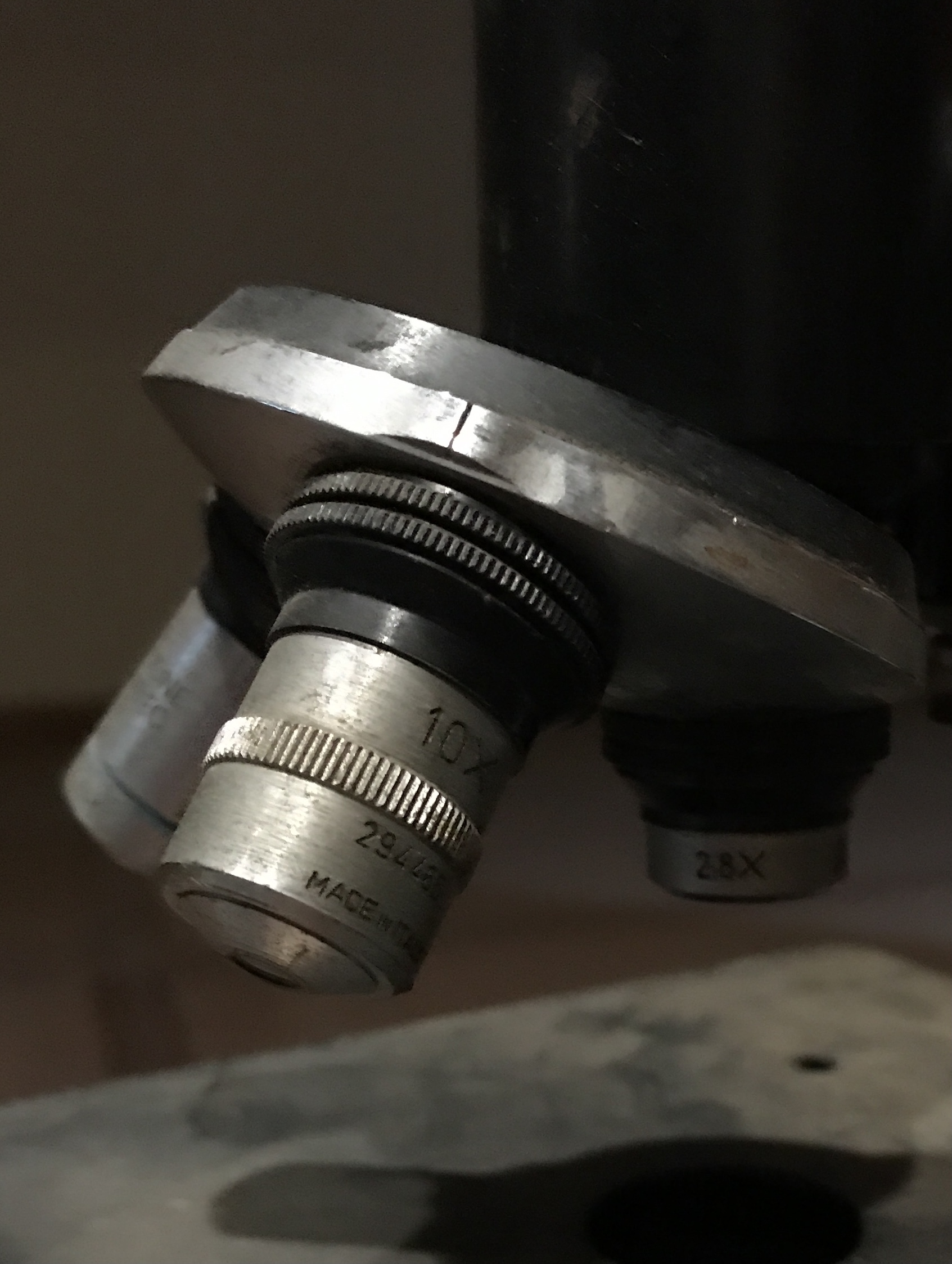
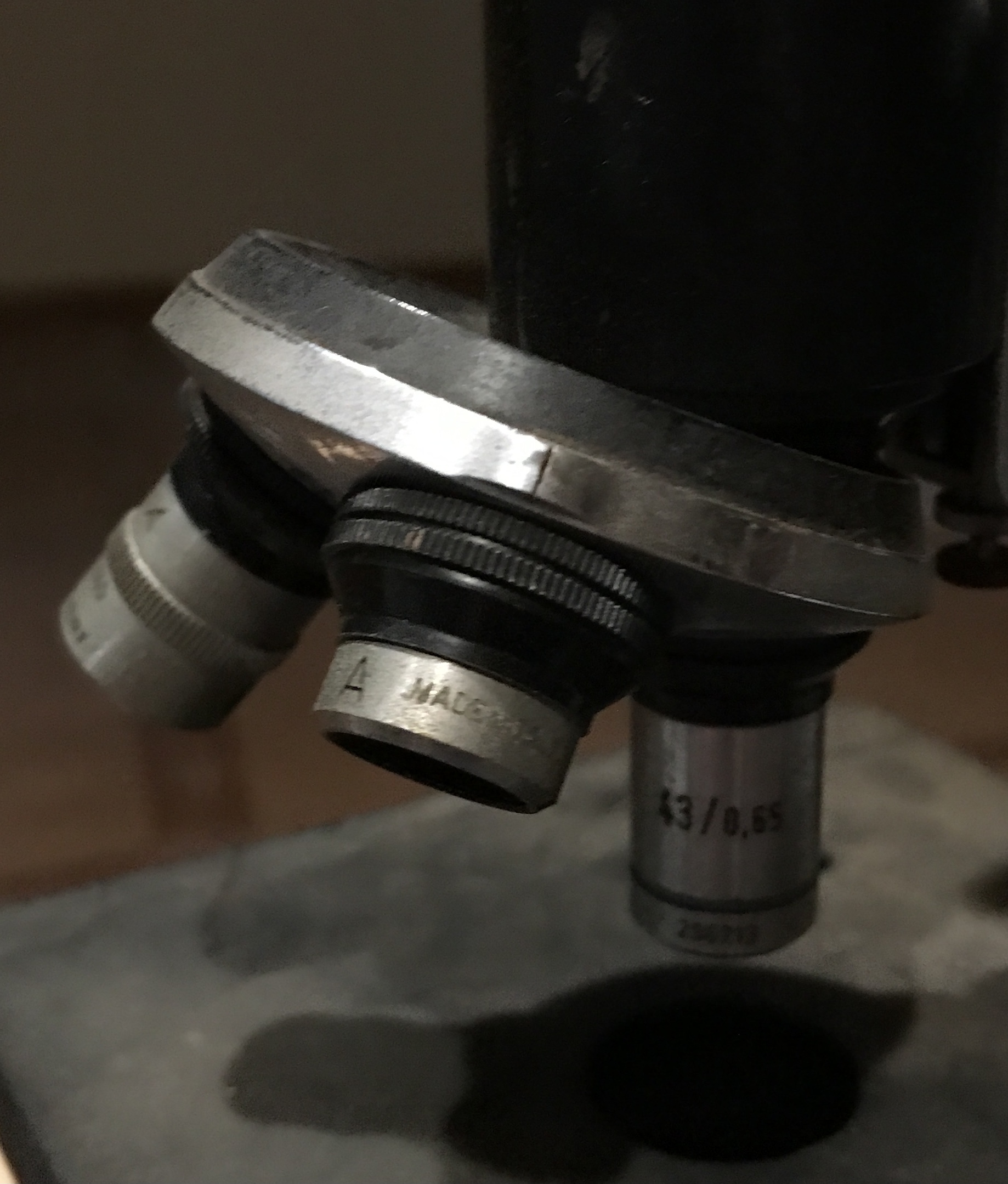
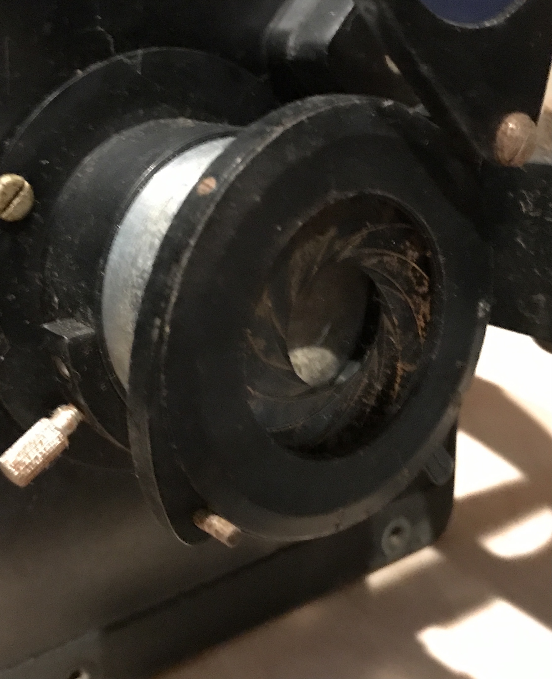
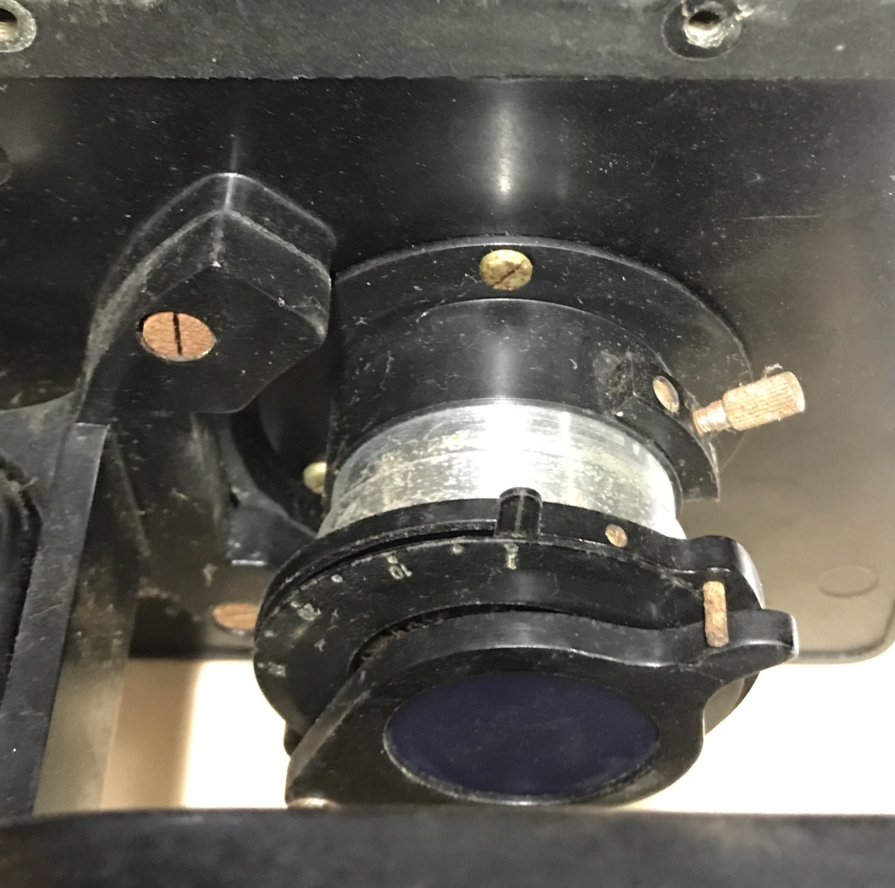
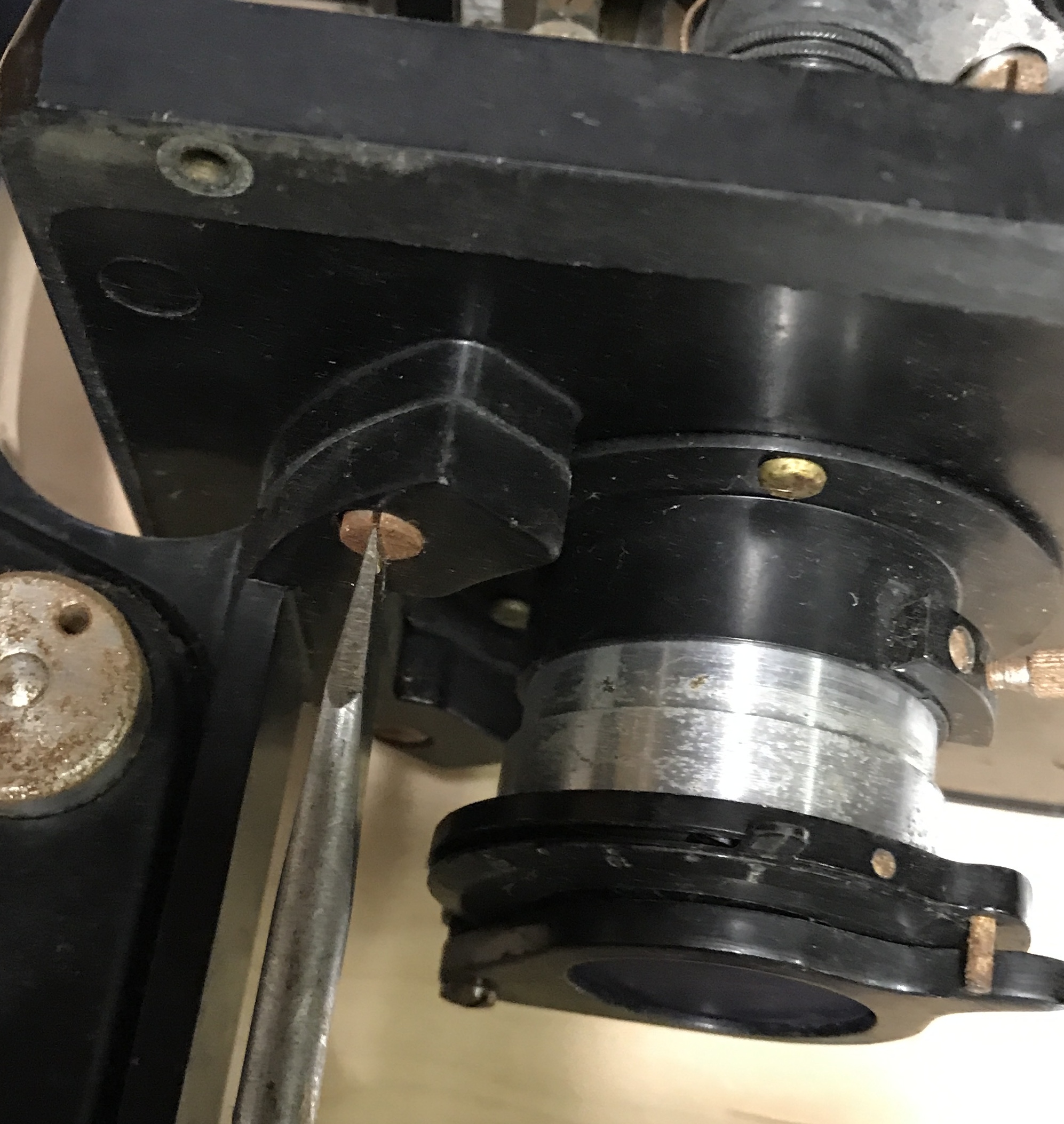
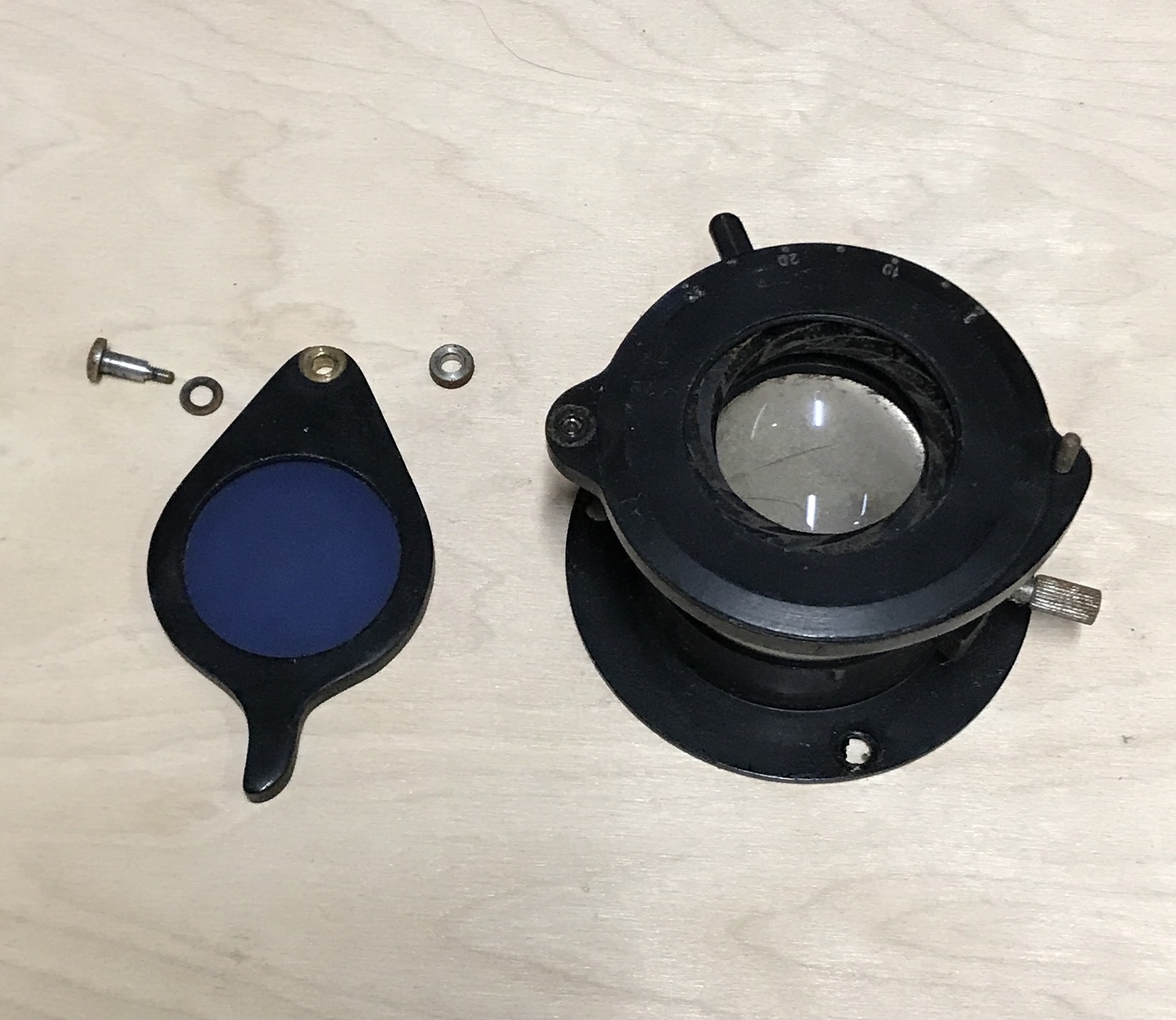
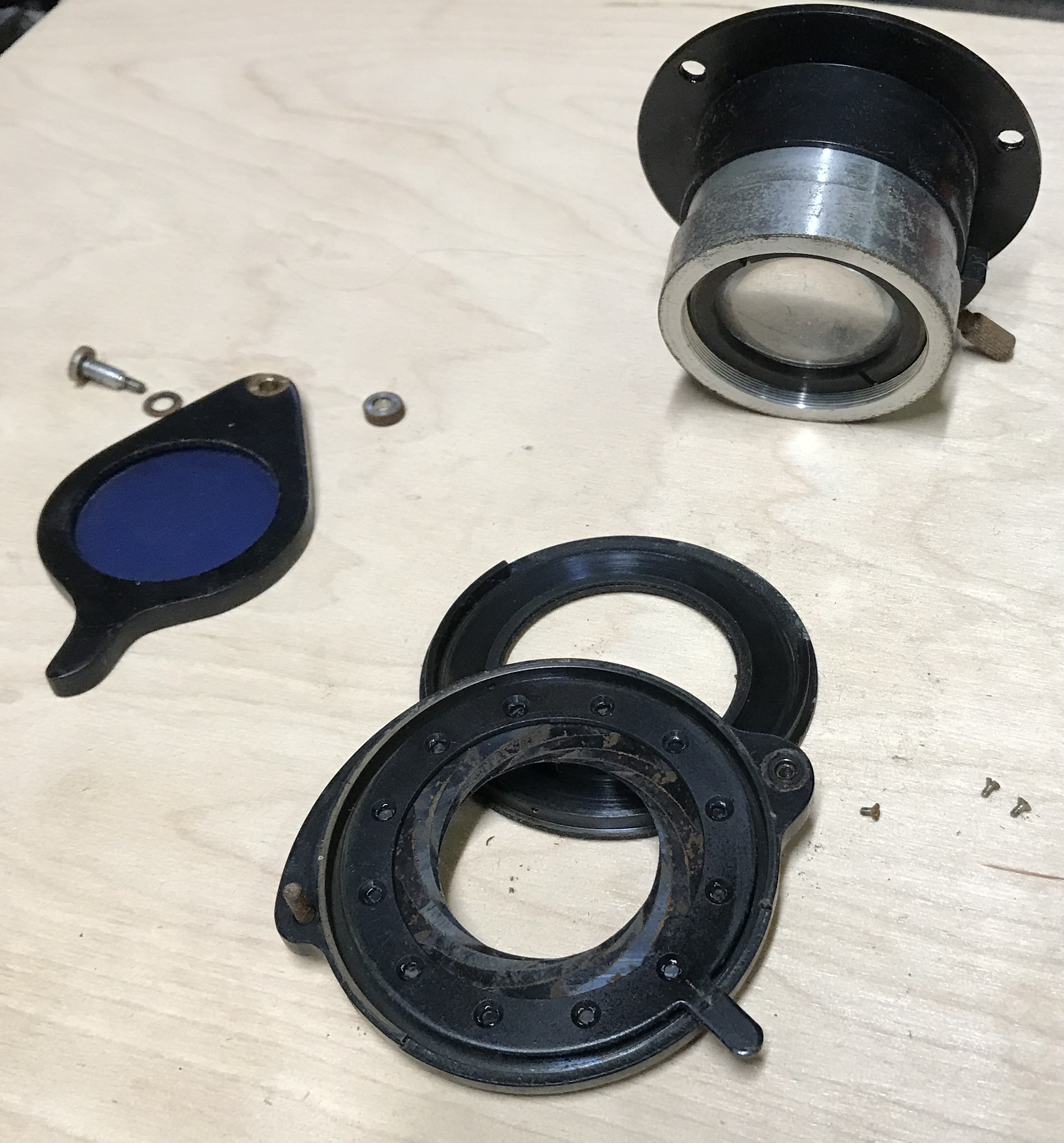
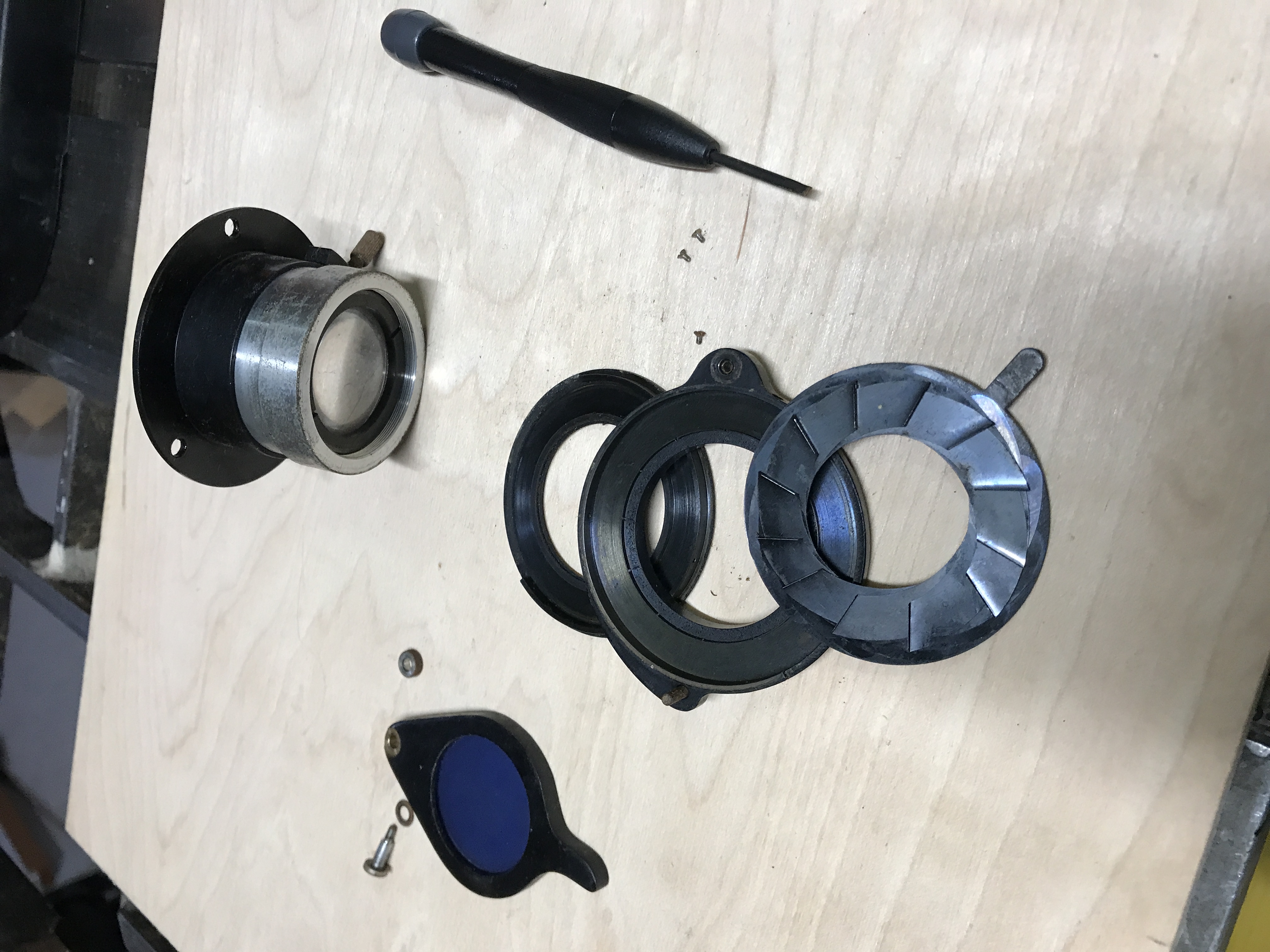
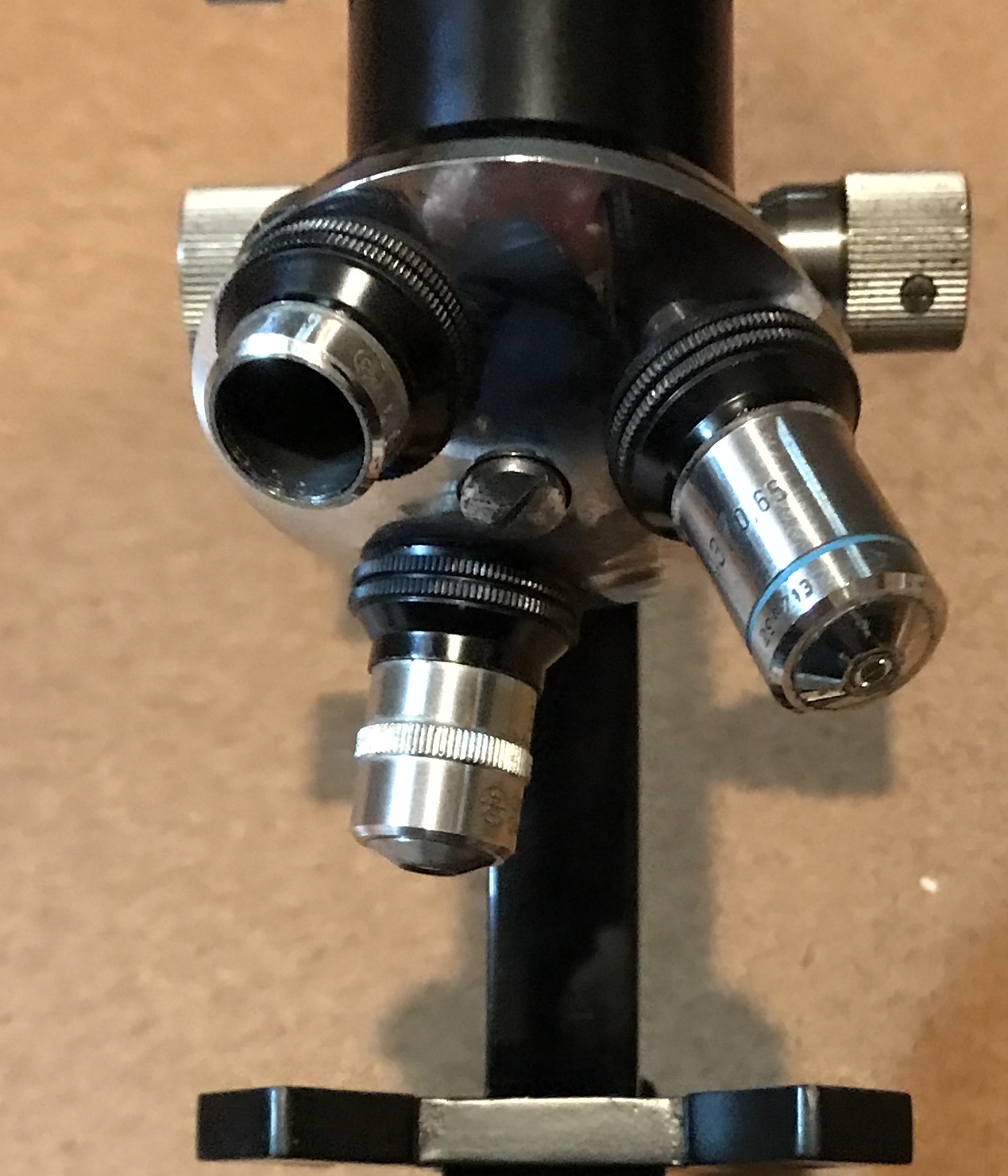
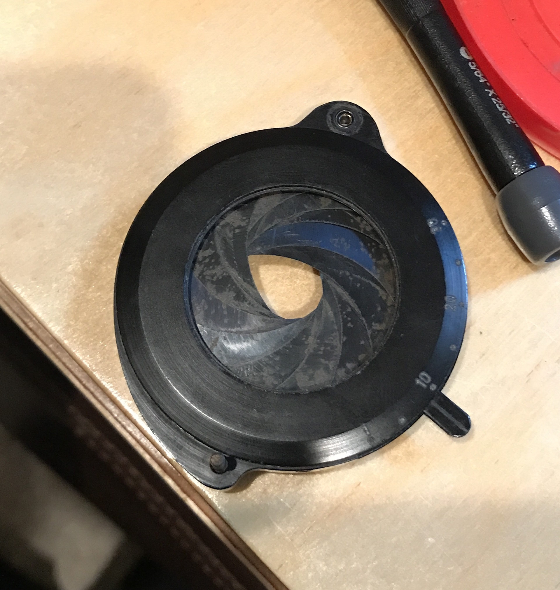
The next two photos show the light management apparatus below the stage or table. It consists of a filter (thought this was a cap initially) and a diaphragm. The two photos after these are of the three lenses. The last of the following five shows the diaphragm with its rust.
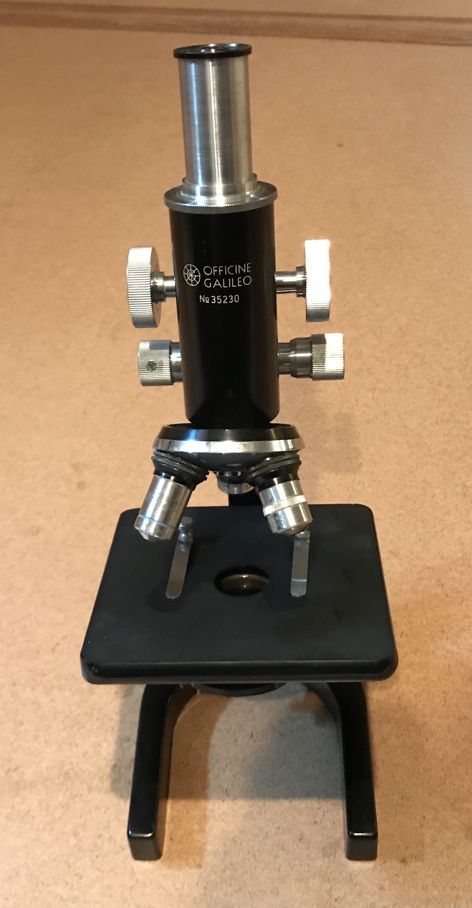
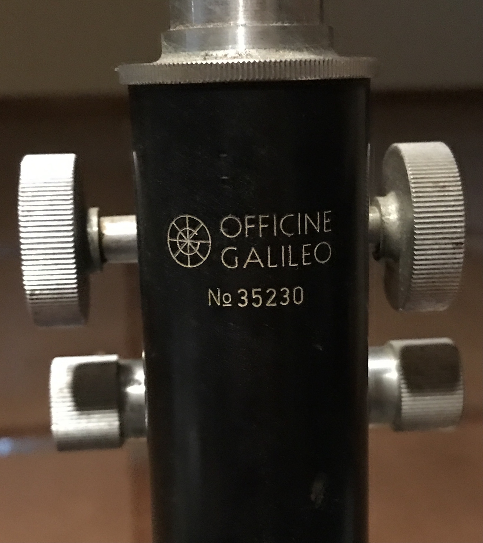
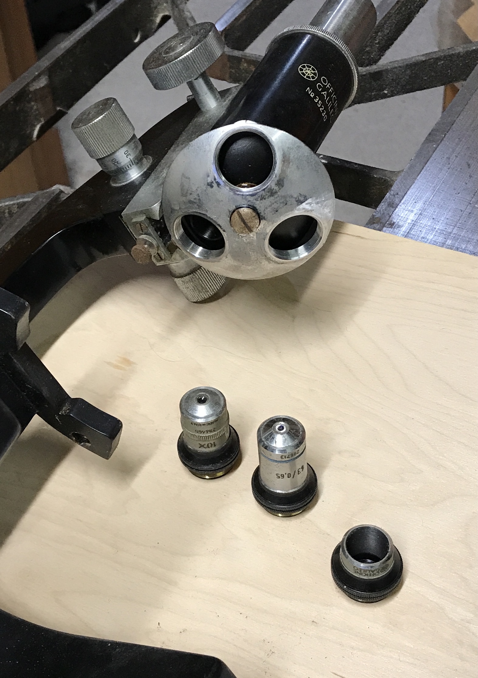
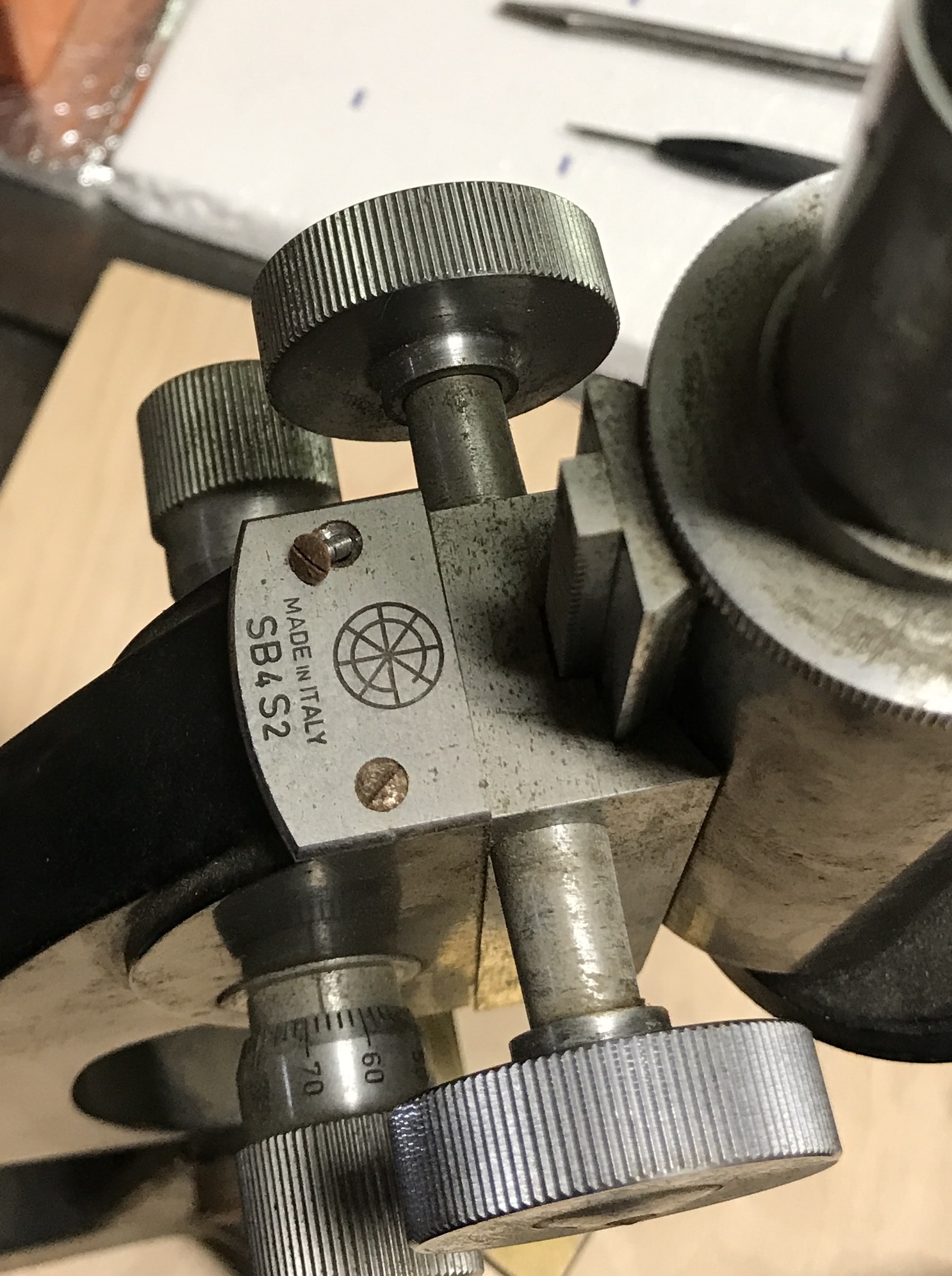
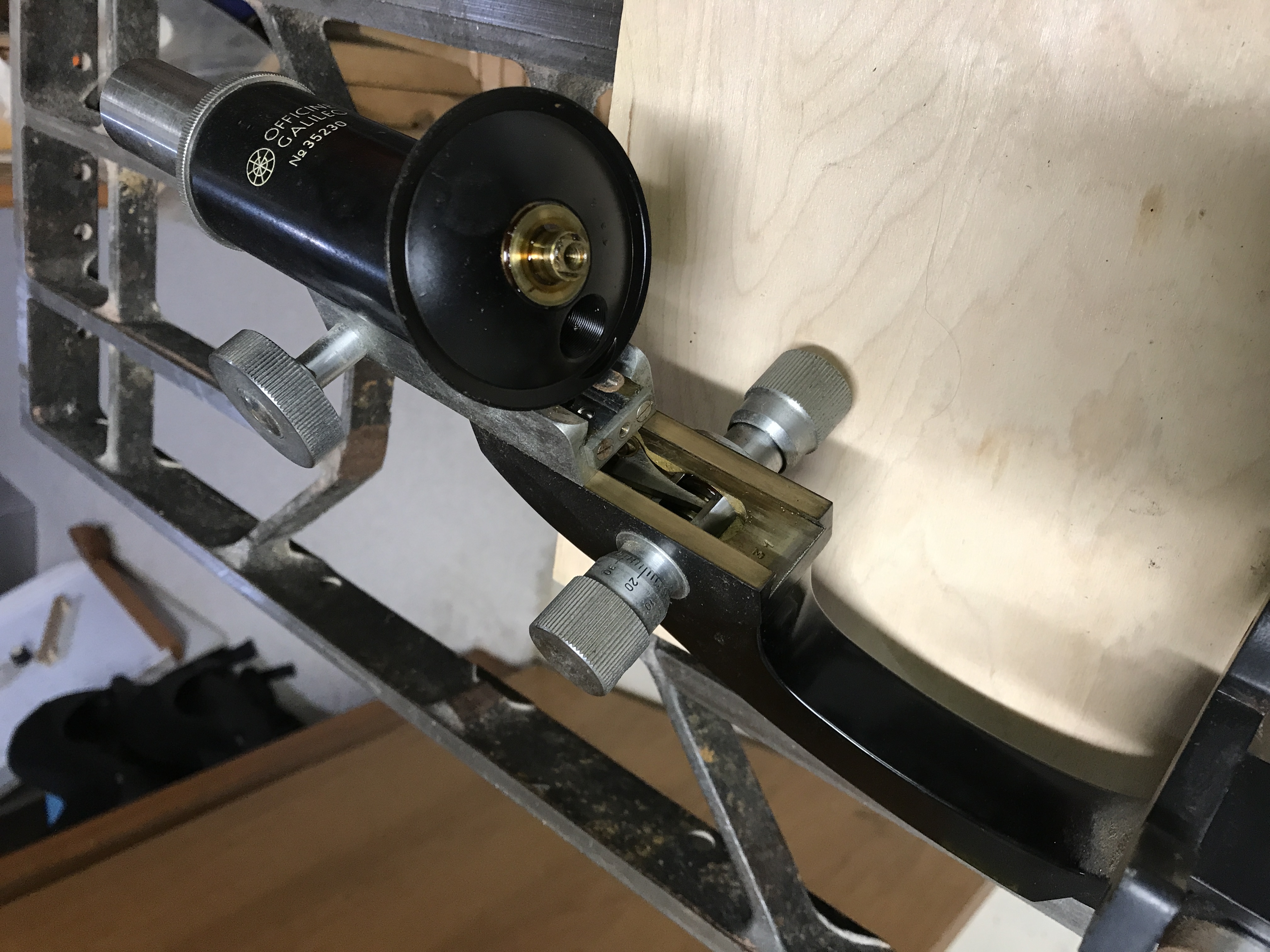
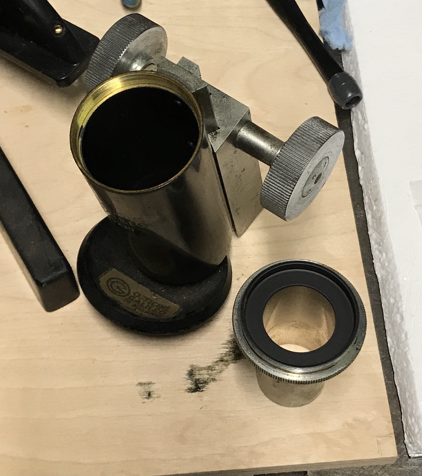
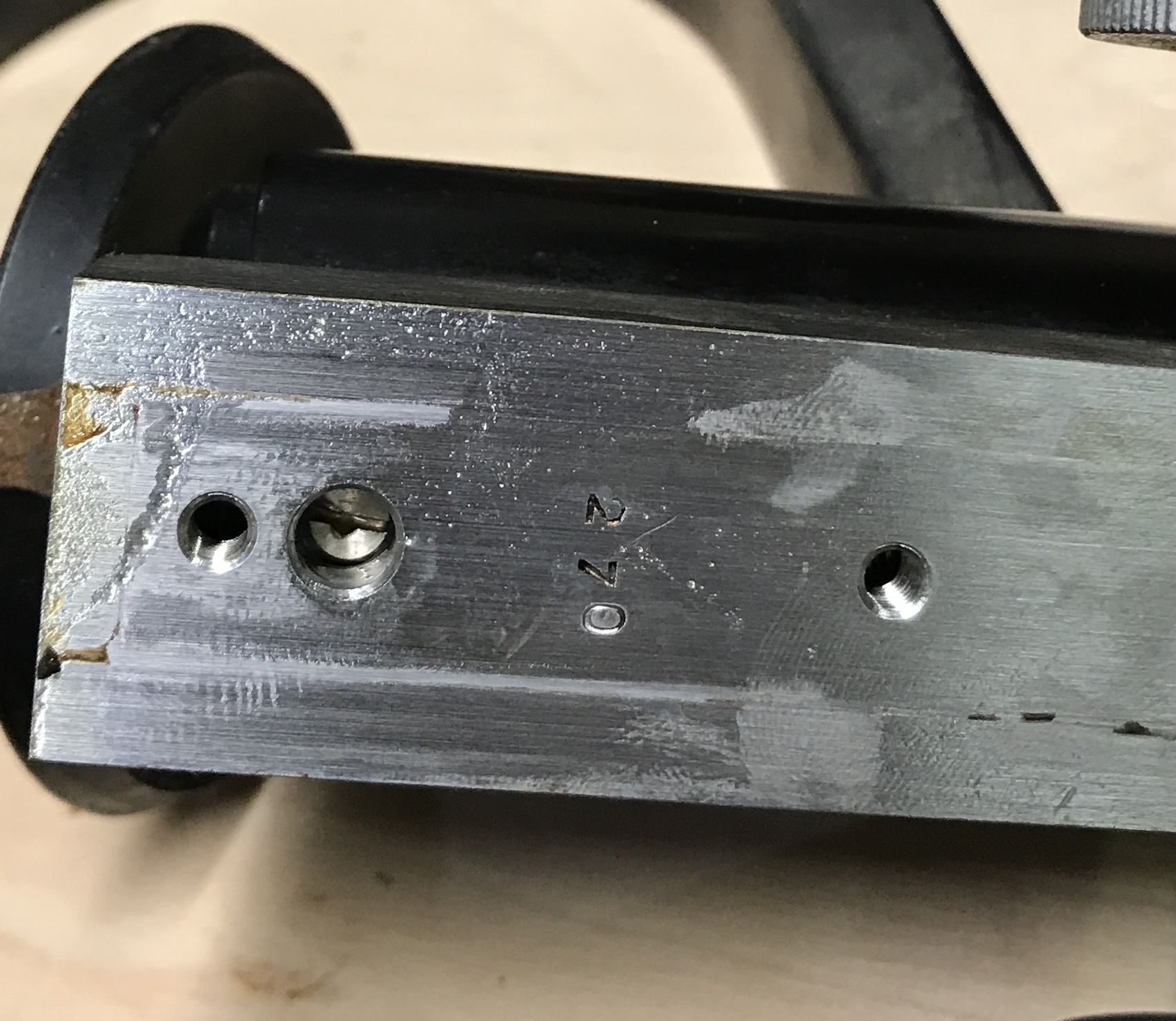
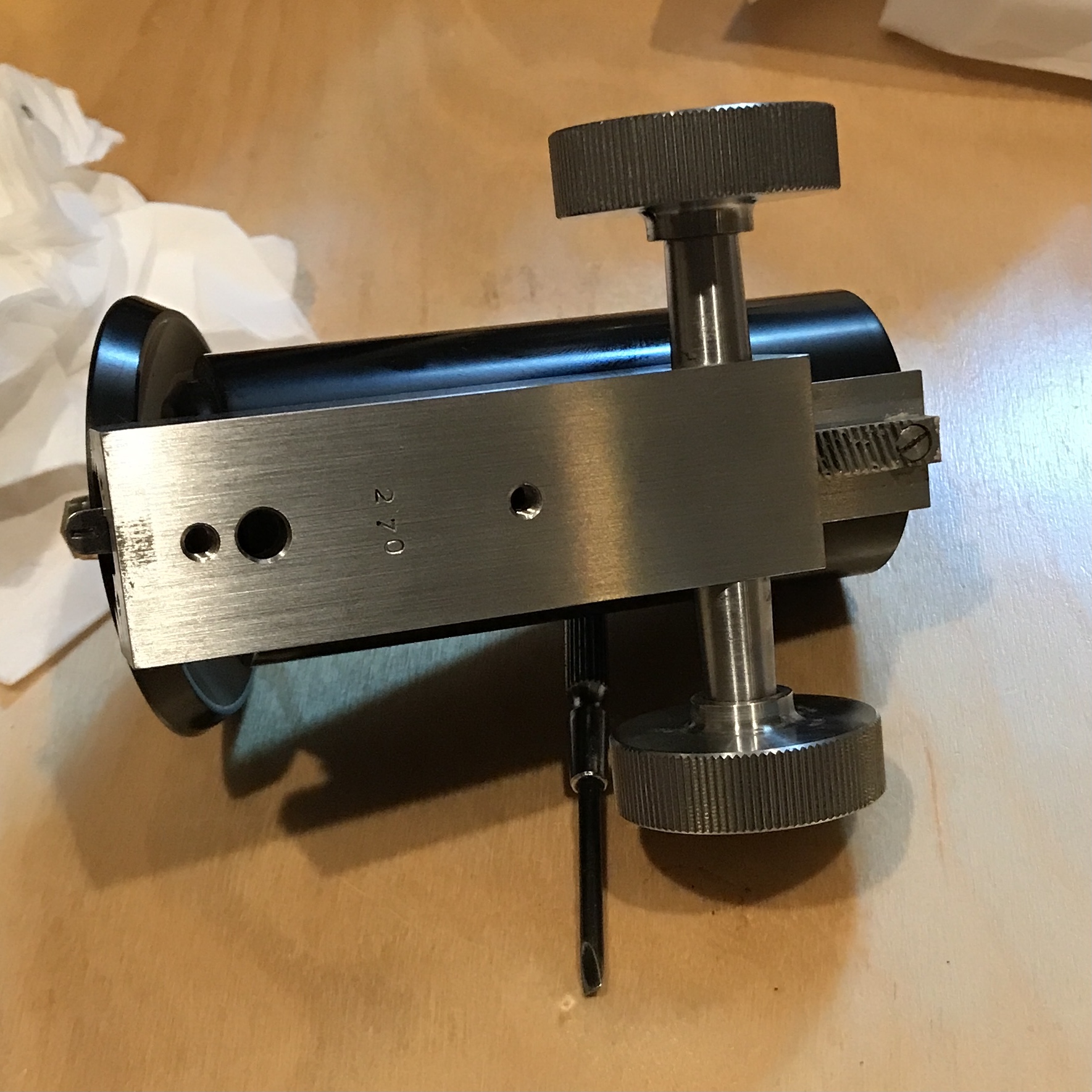
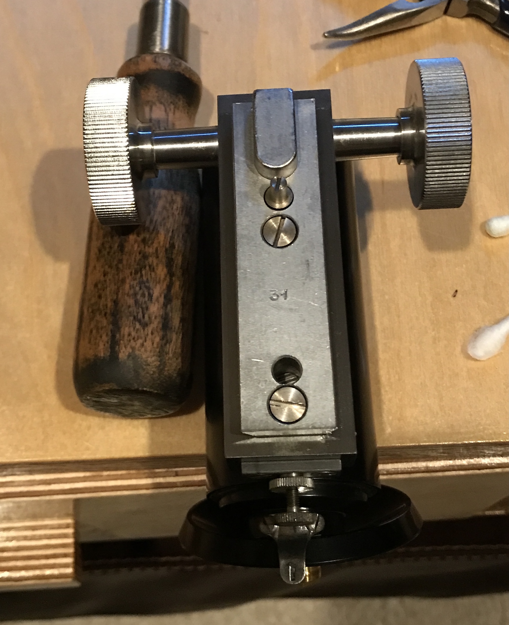
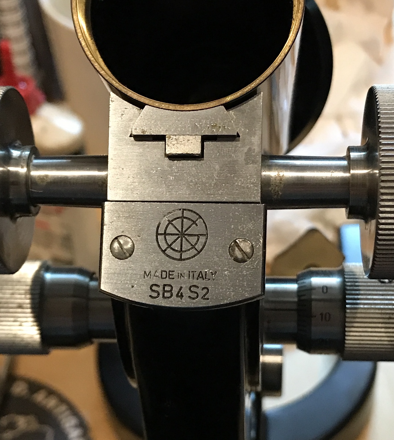
The next photo shows the name of the Italian company, Officine Galileo, that made the microscope. They are a well known maker of scientific instruments. The serial number is also shown. I saw similar microscopes for sale on the internet from the same company. They had much higher serial numbers and were made in the 60's.
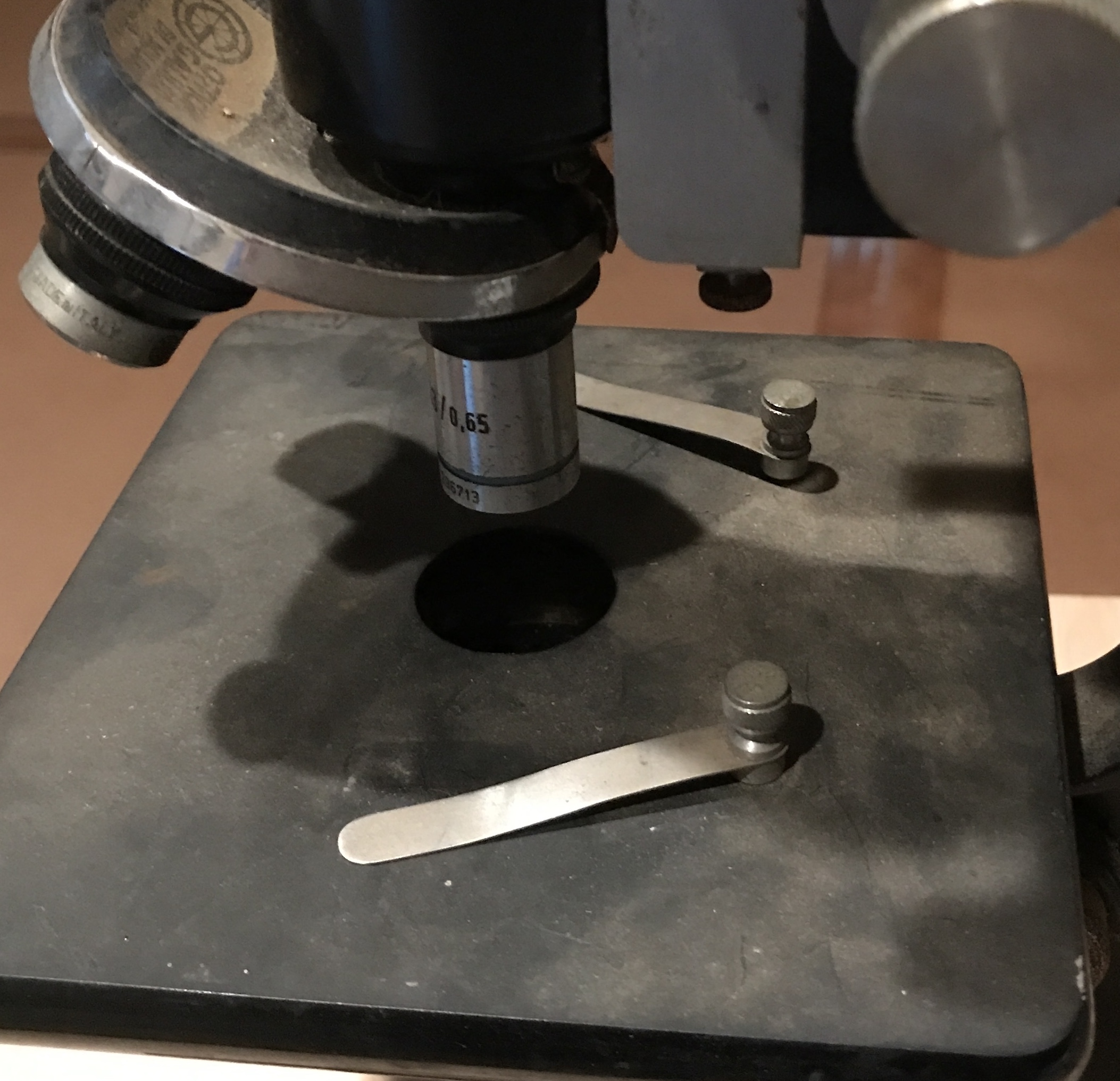
This photo shows the stage with the two slide clips installed.
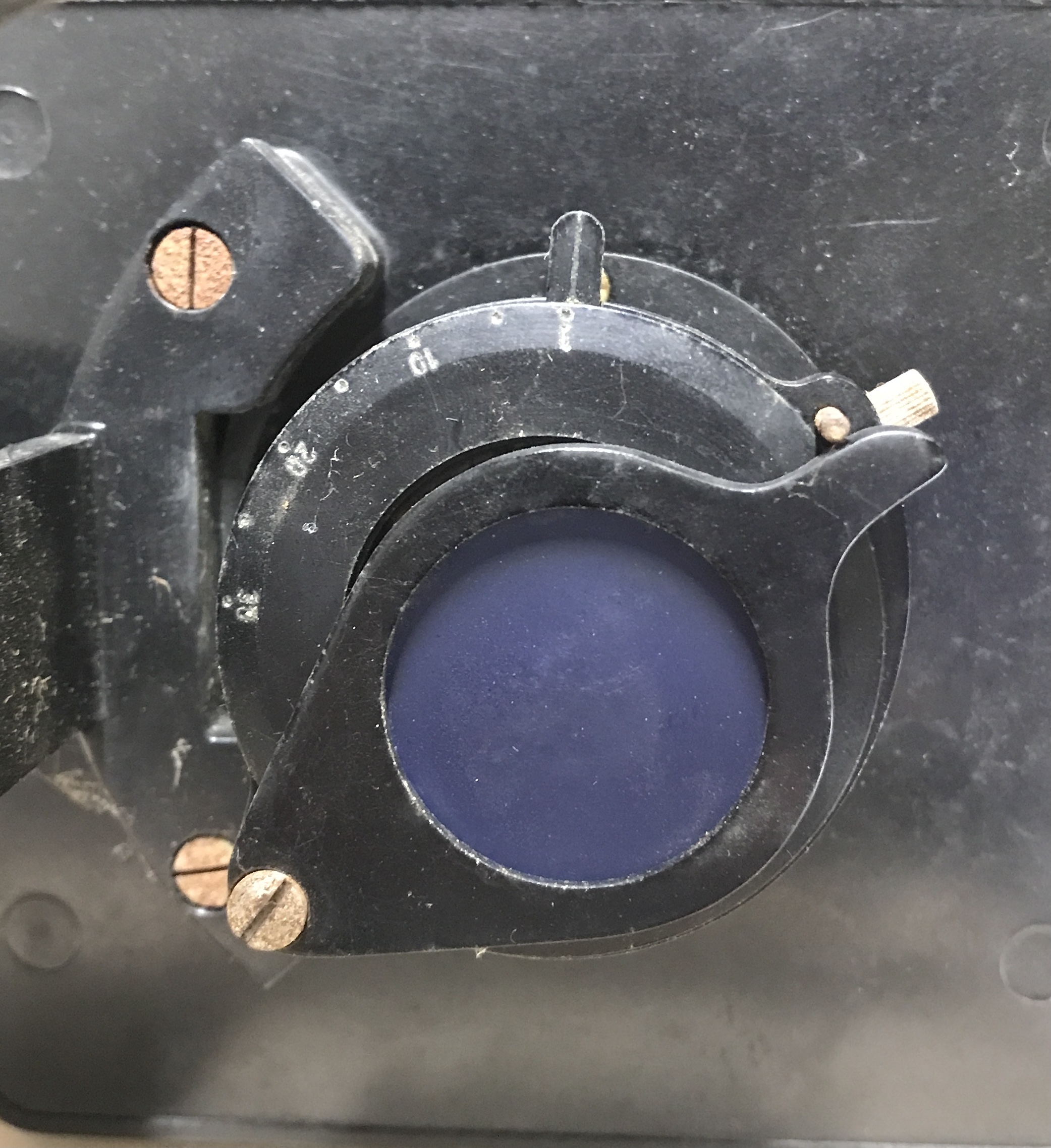
The next photo shows the filter on the light stage. It is blue glass, which I didn't realize until it was removed. The glass is easily replaced, implying the microscope came with interchangeable filters.
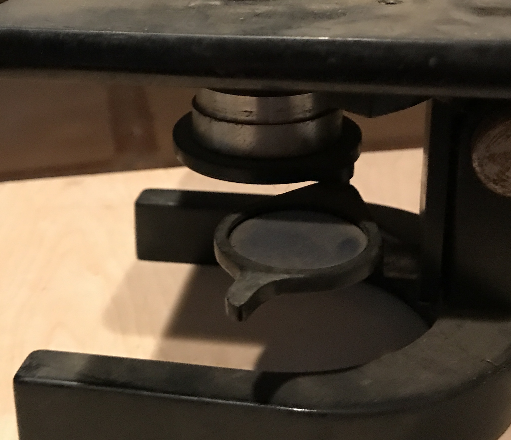
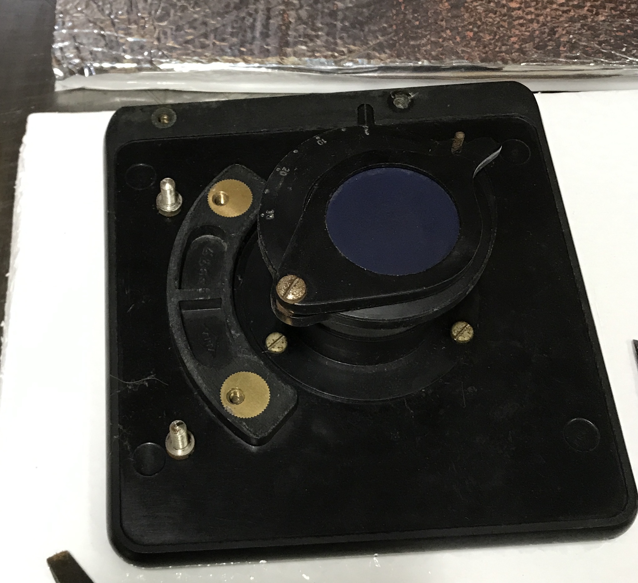
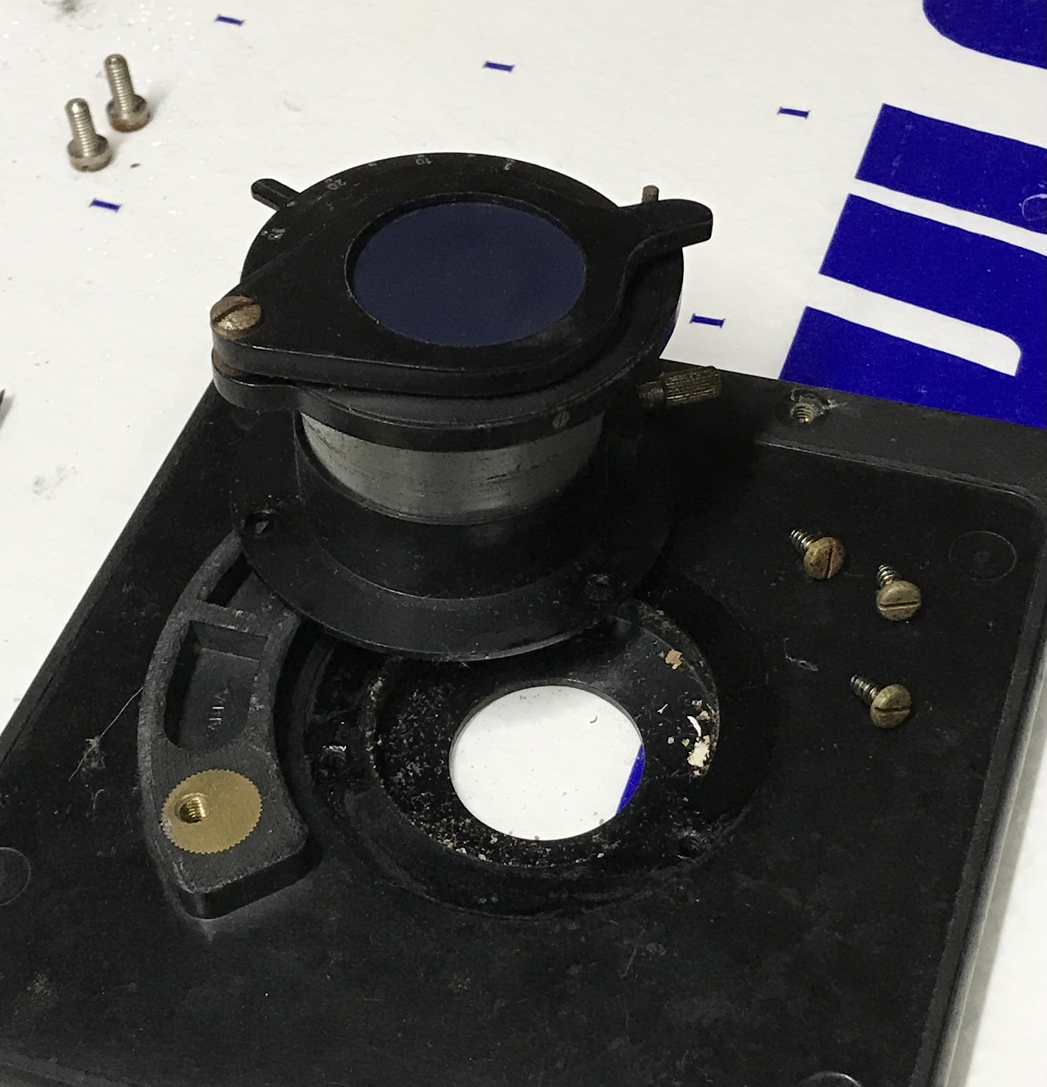
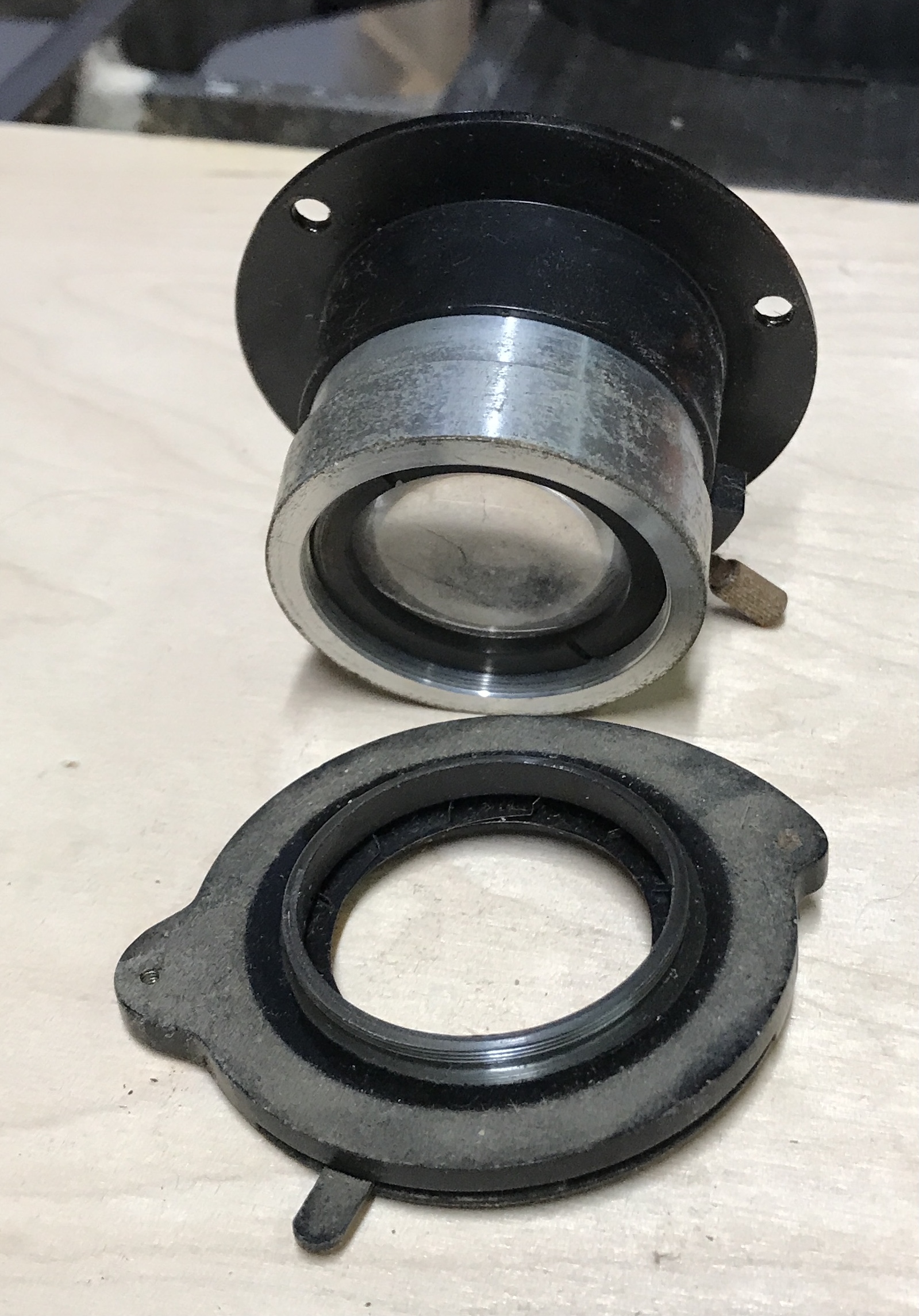
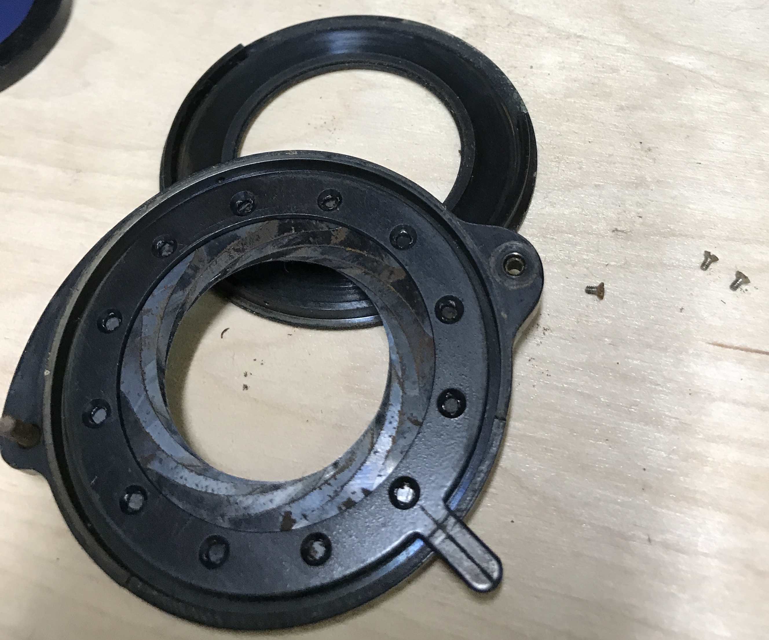
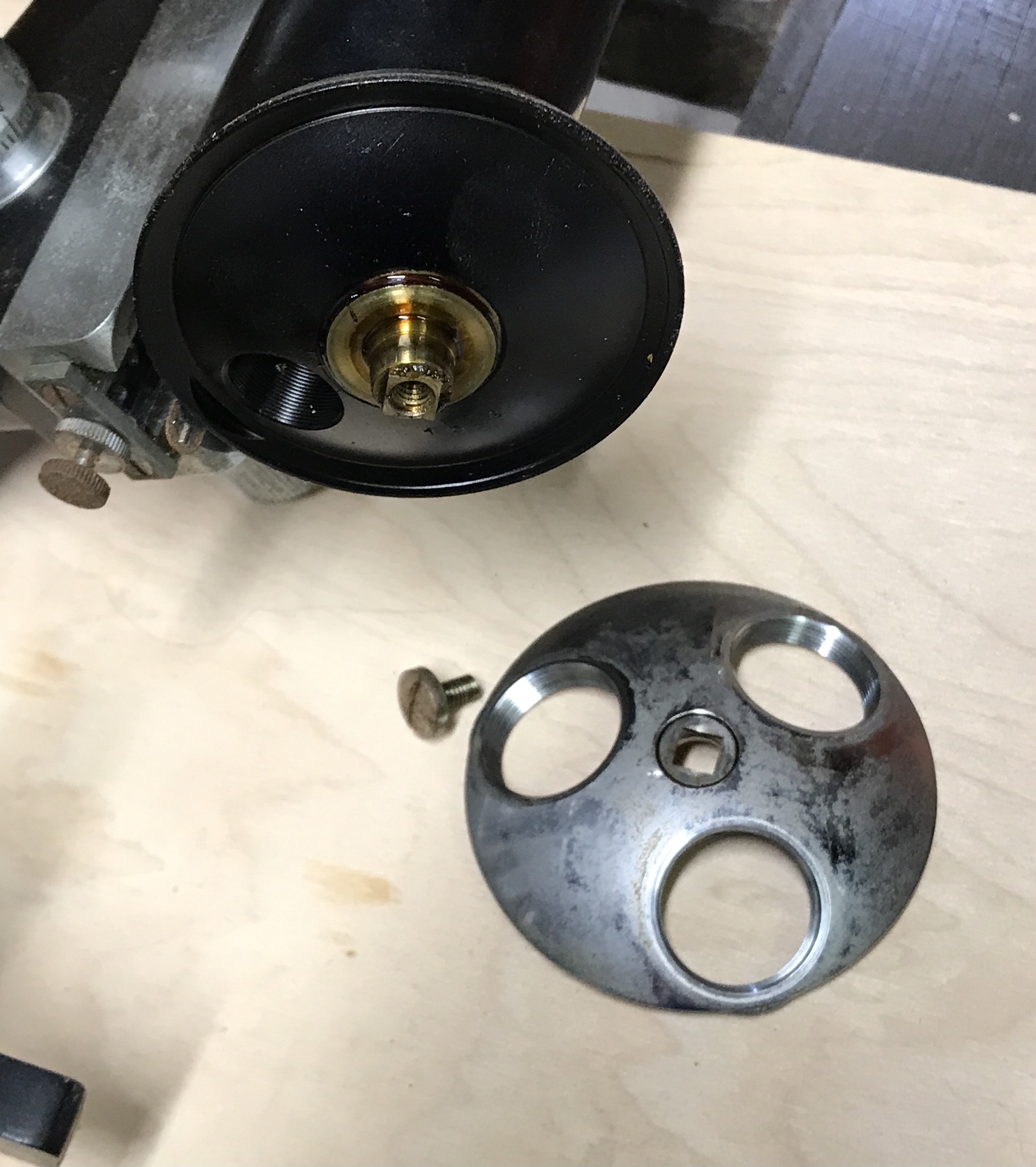
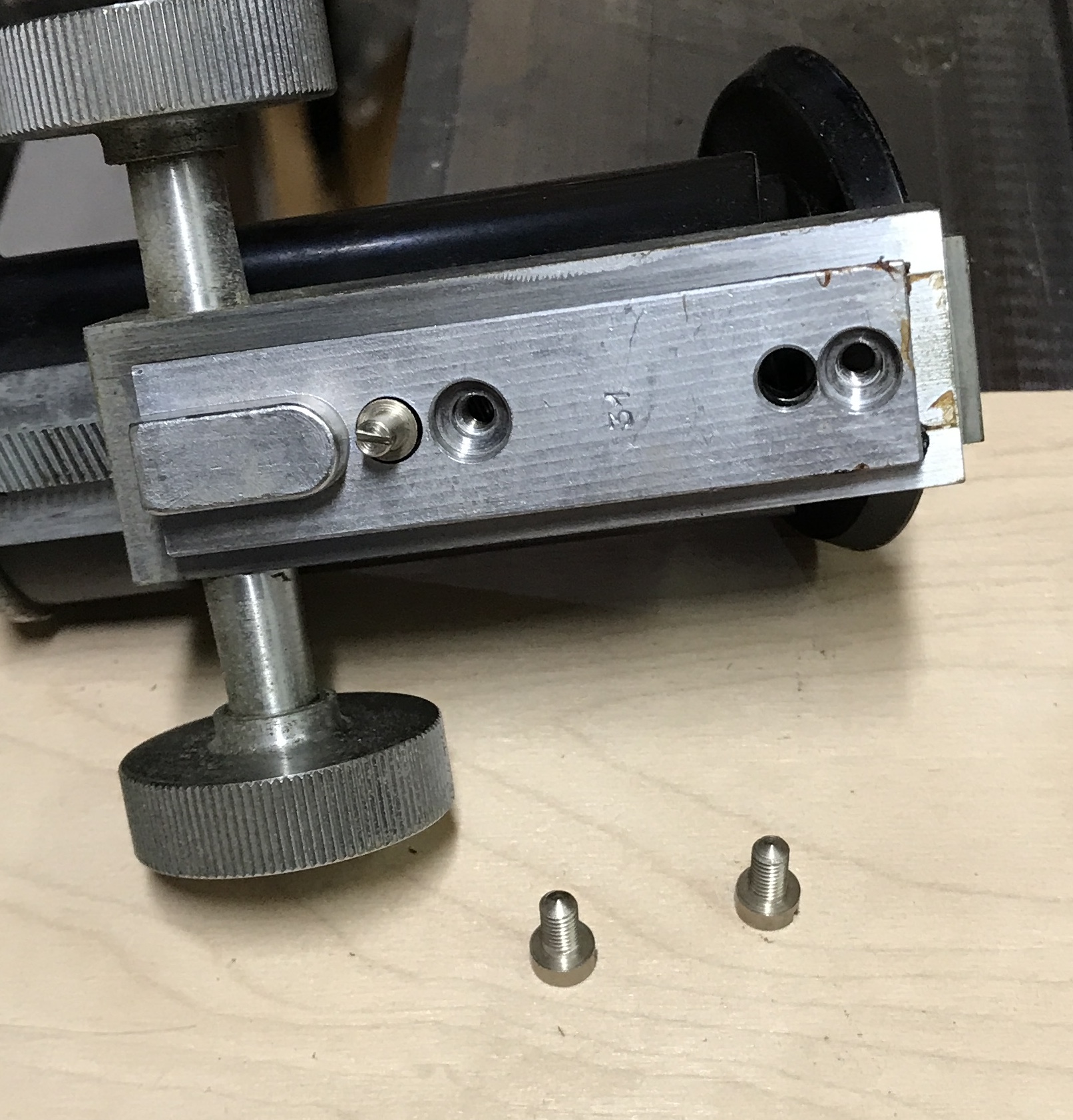
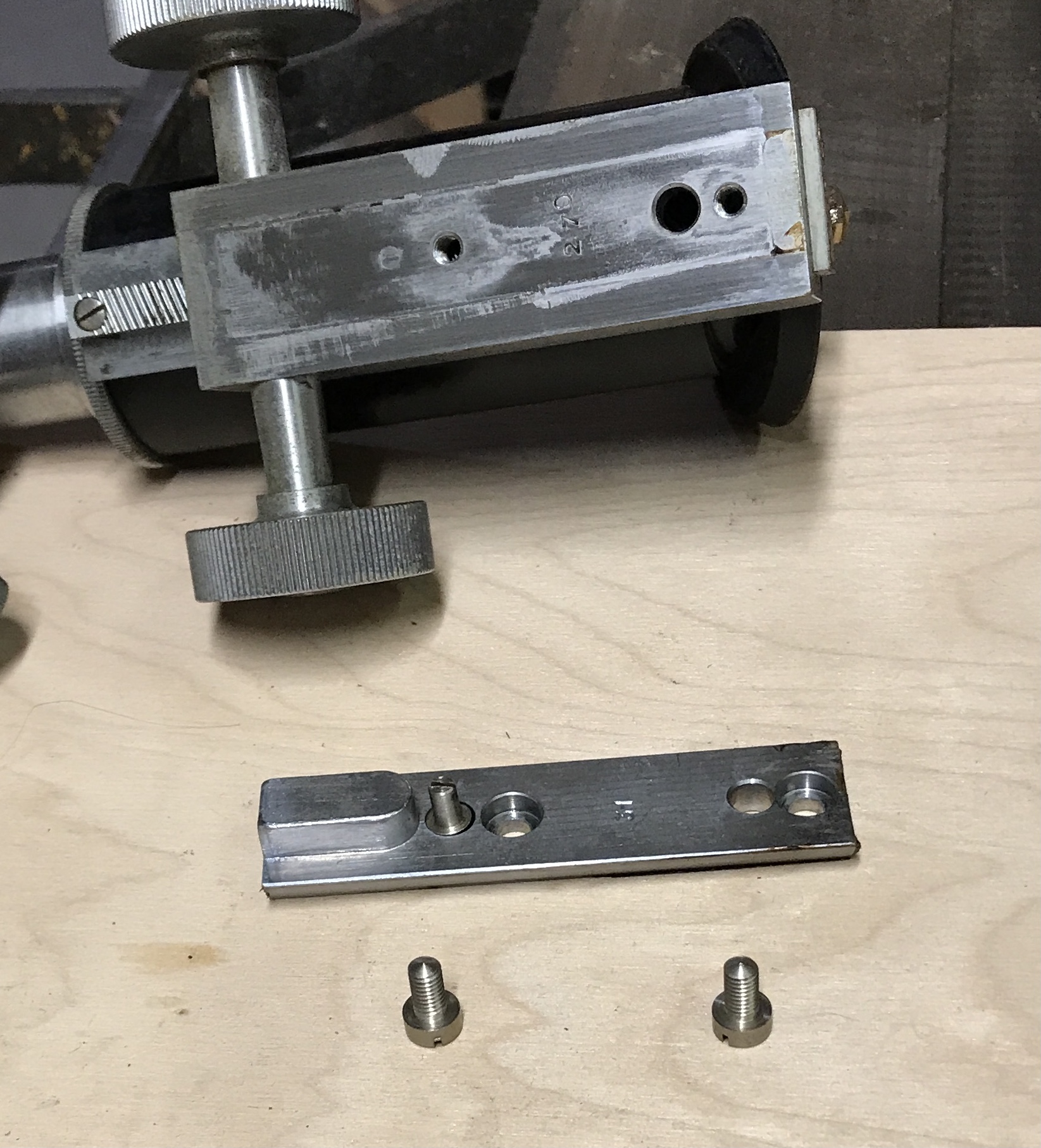
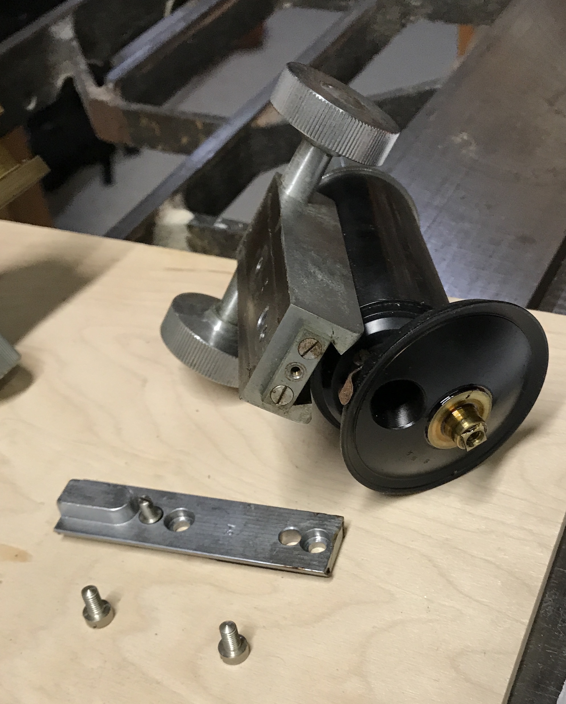
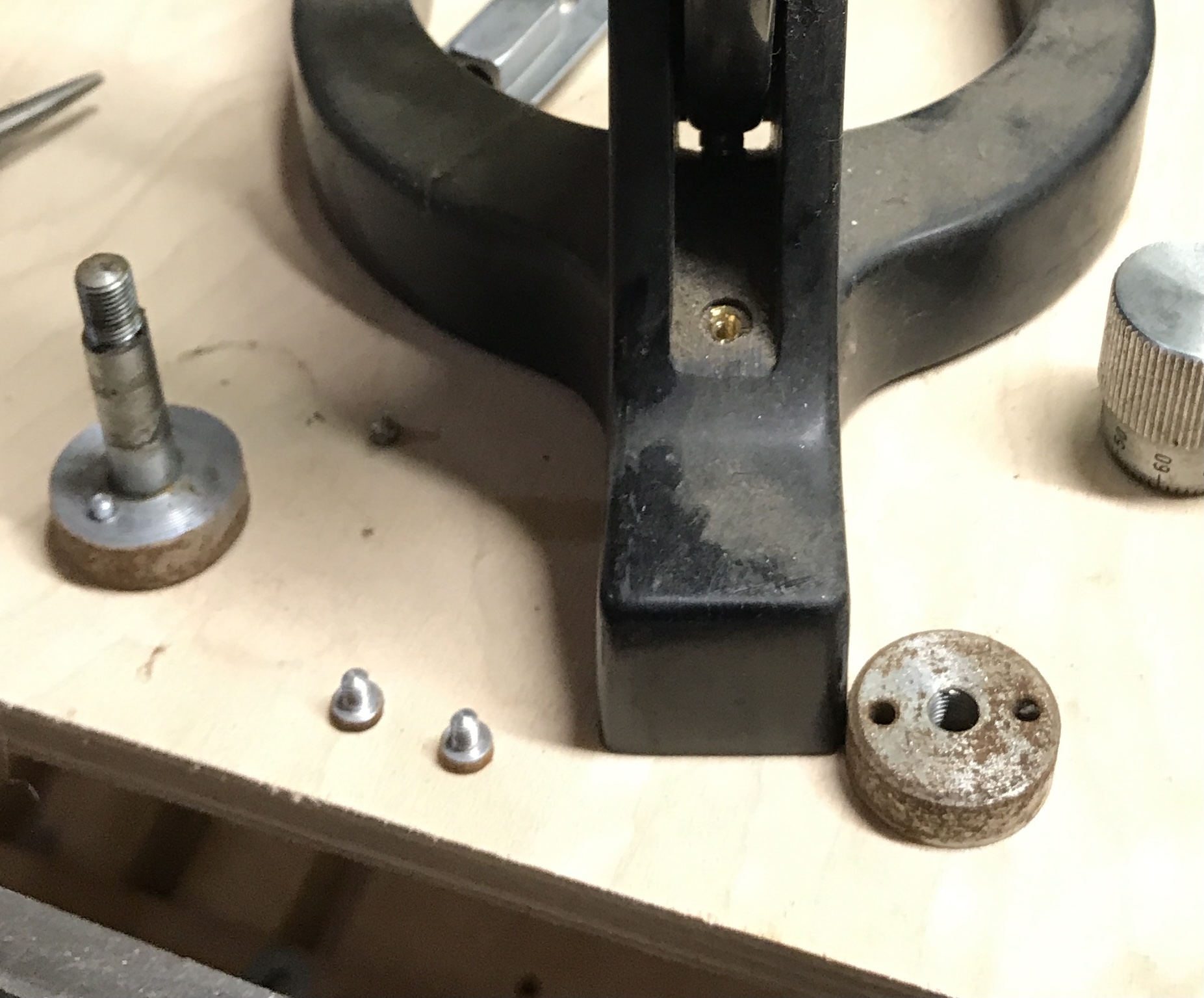
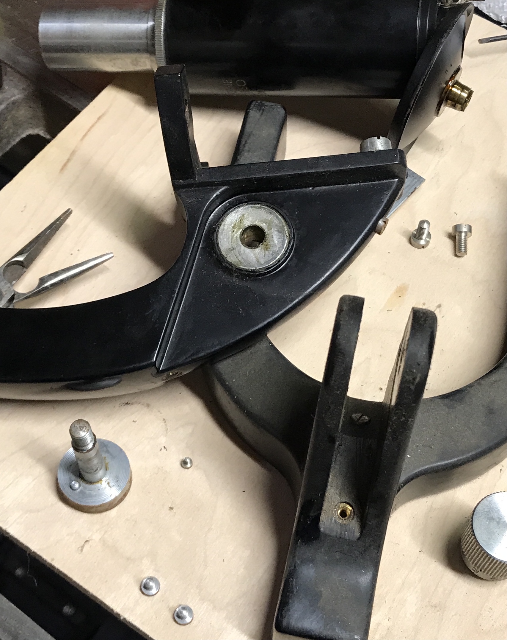
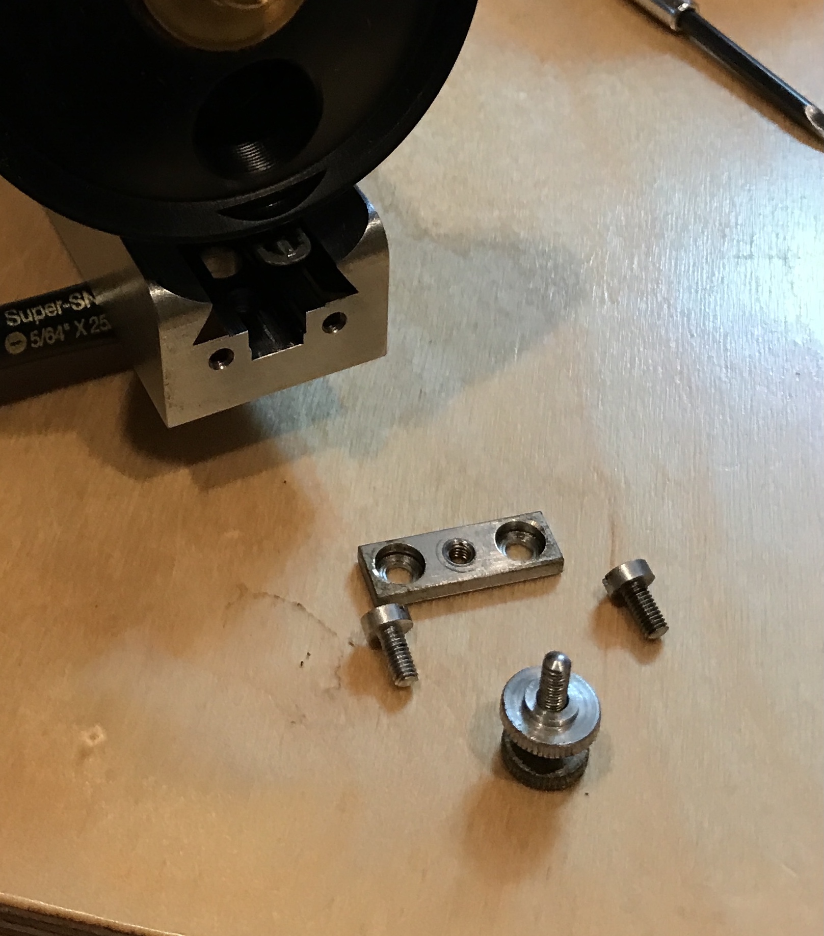
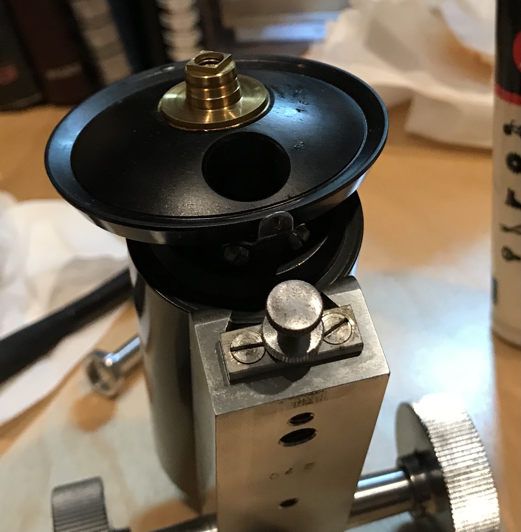
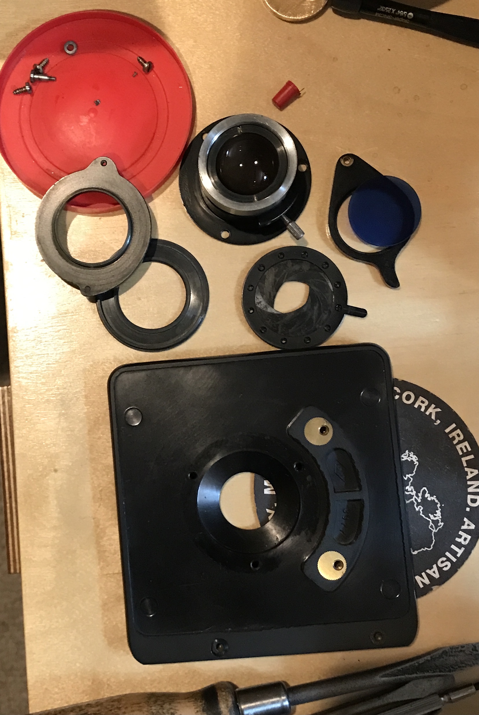
The next sequence of ten photos documents the removal of the light stage and taking it apart. The two large screws were removed first. These screws hold the stage in place. Three smaller screws hold the light management apparatus to the stage. The filter holder was held in place with one screw that had a unique washer embedded in the hole. The diaphragm was unscrewed from the light focusing lens. The diaphragm unscrewed from its holder. Notice the three tiny screws. The last photo shows the tiny screws held by a magnet so they won't get lost.
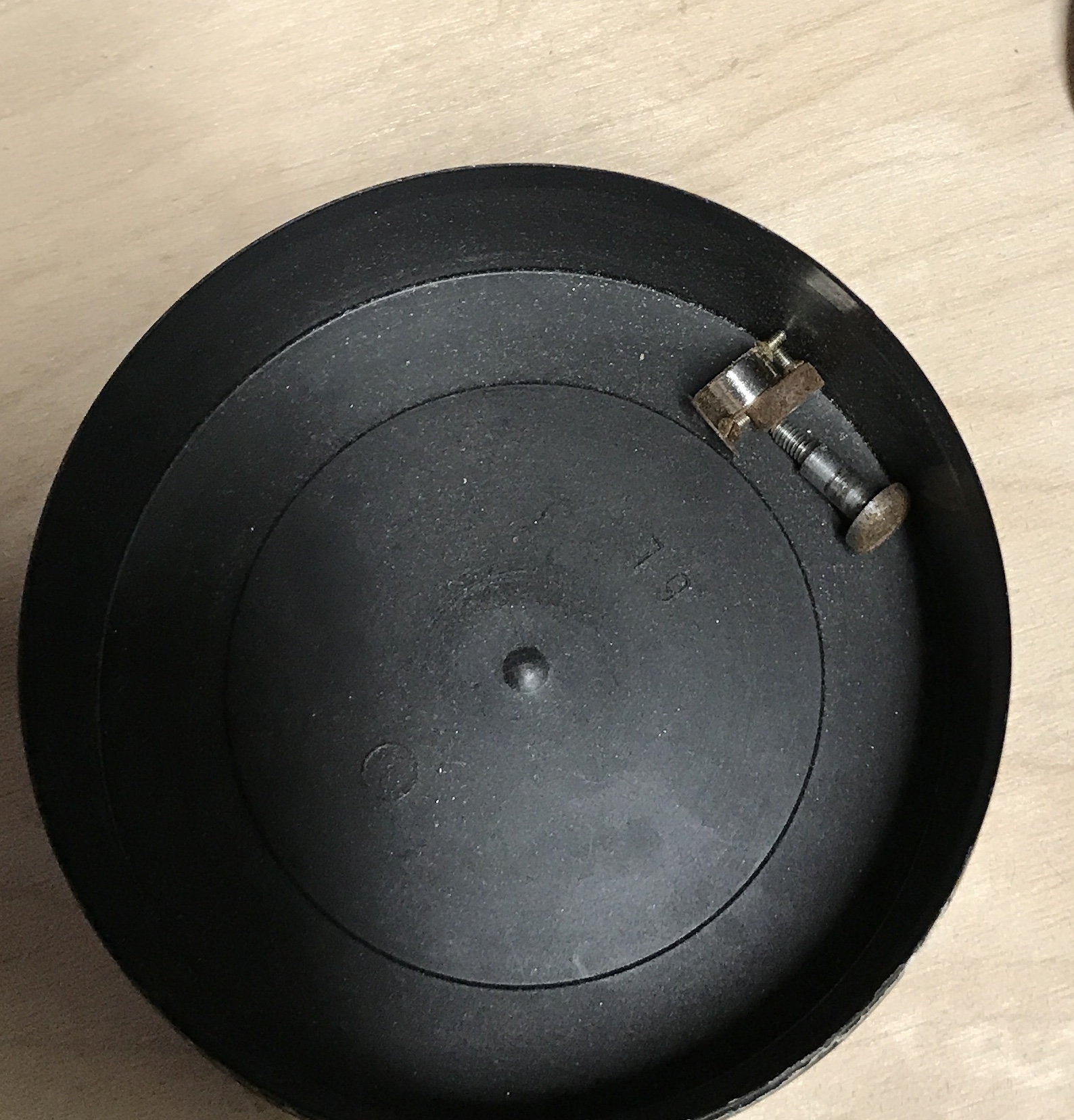
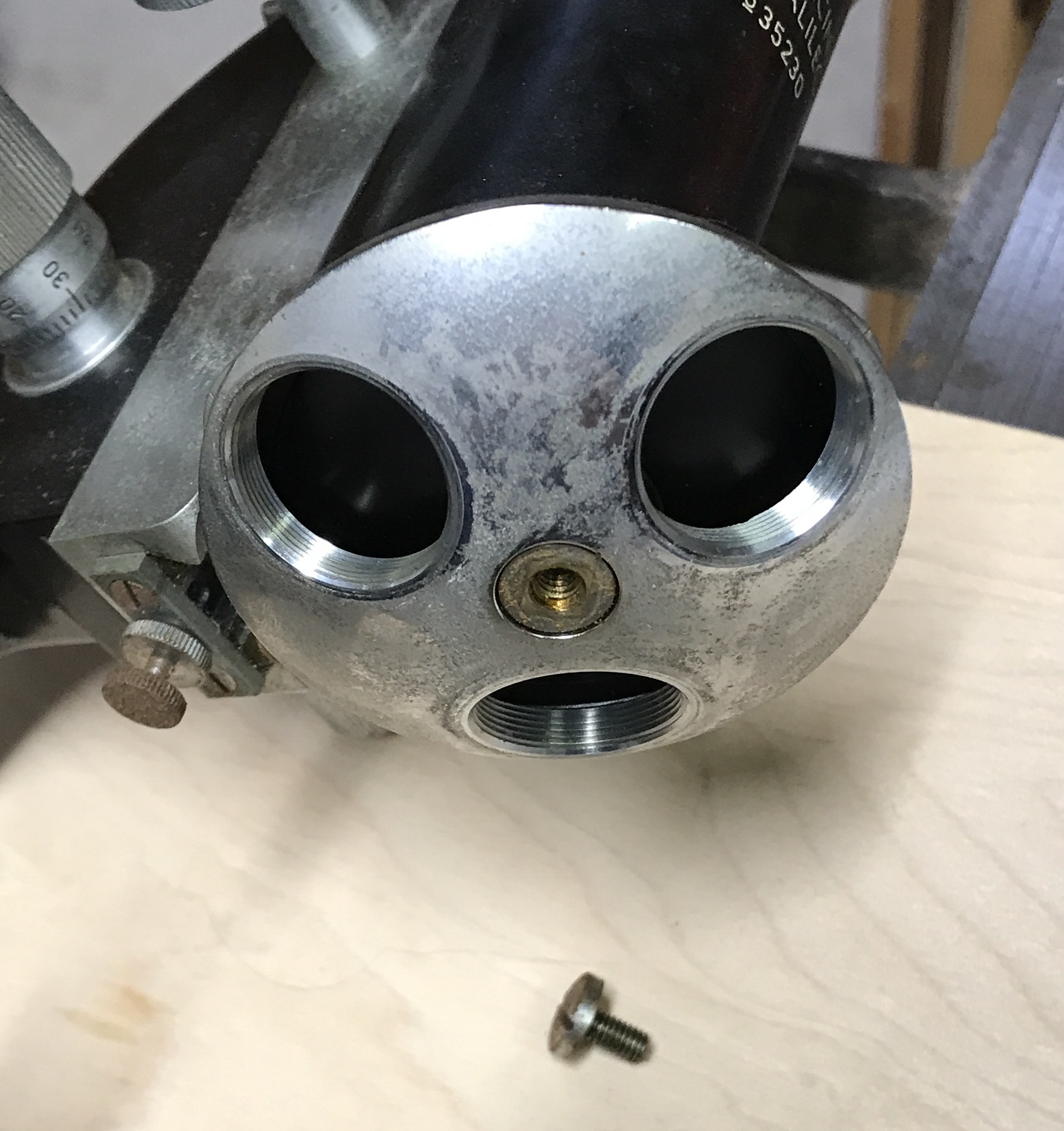
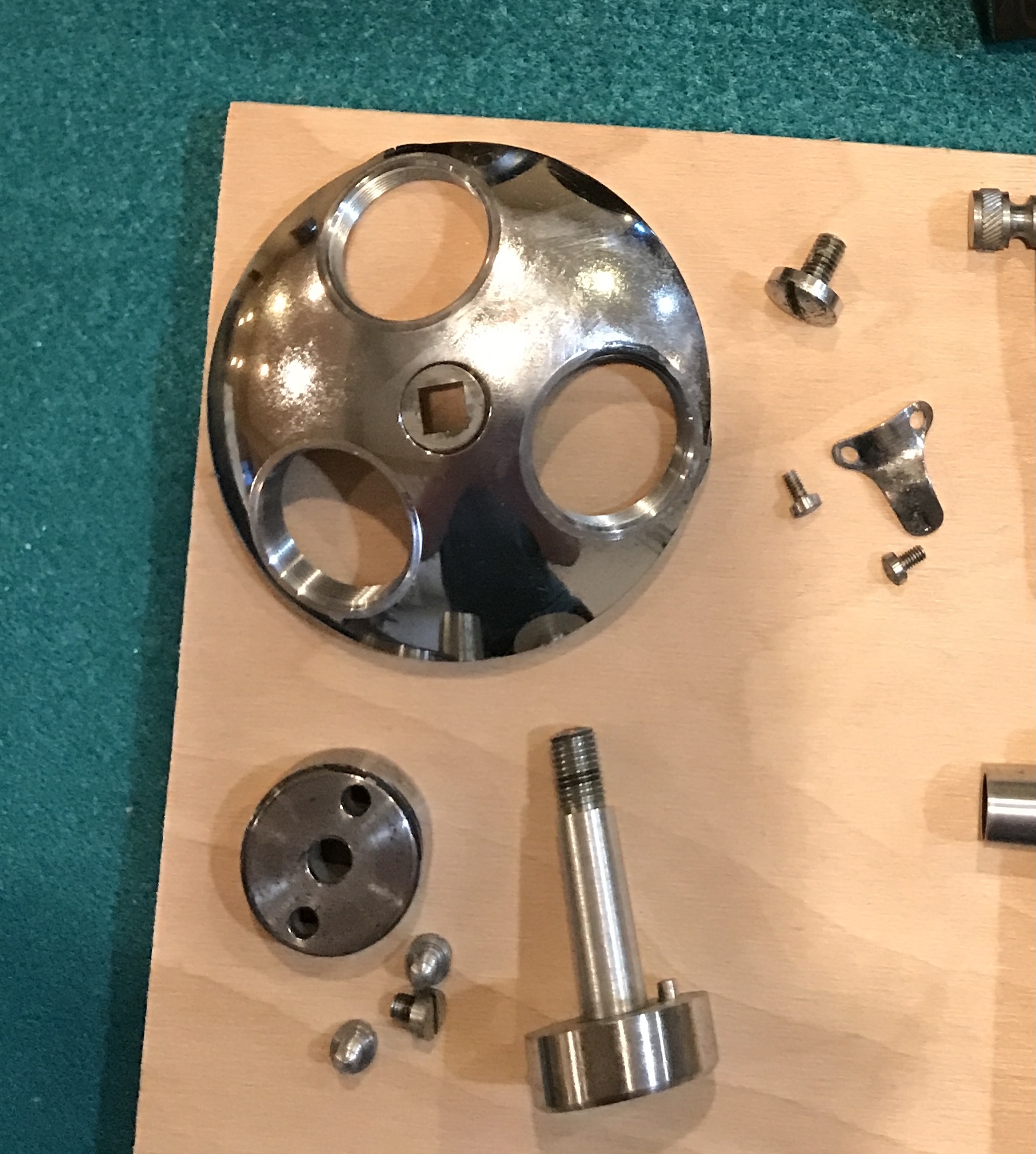
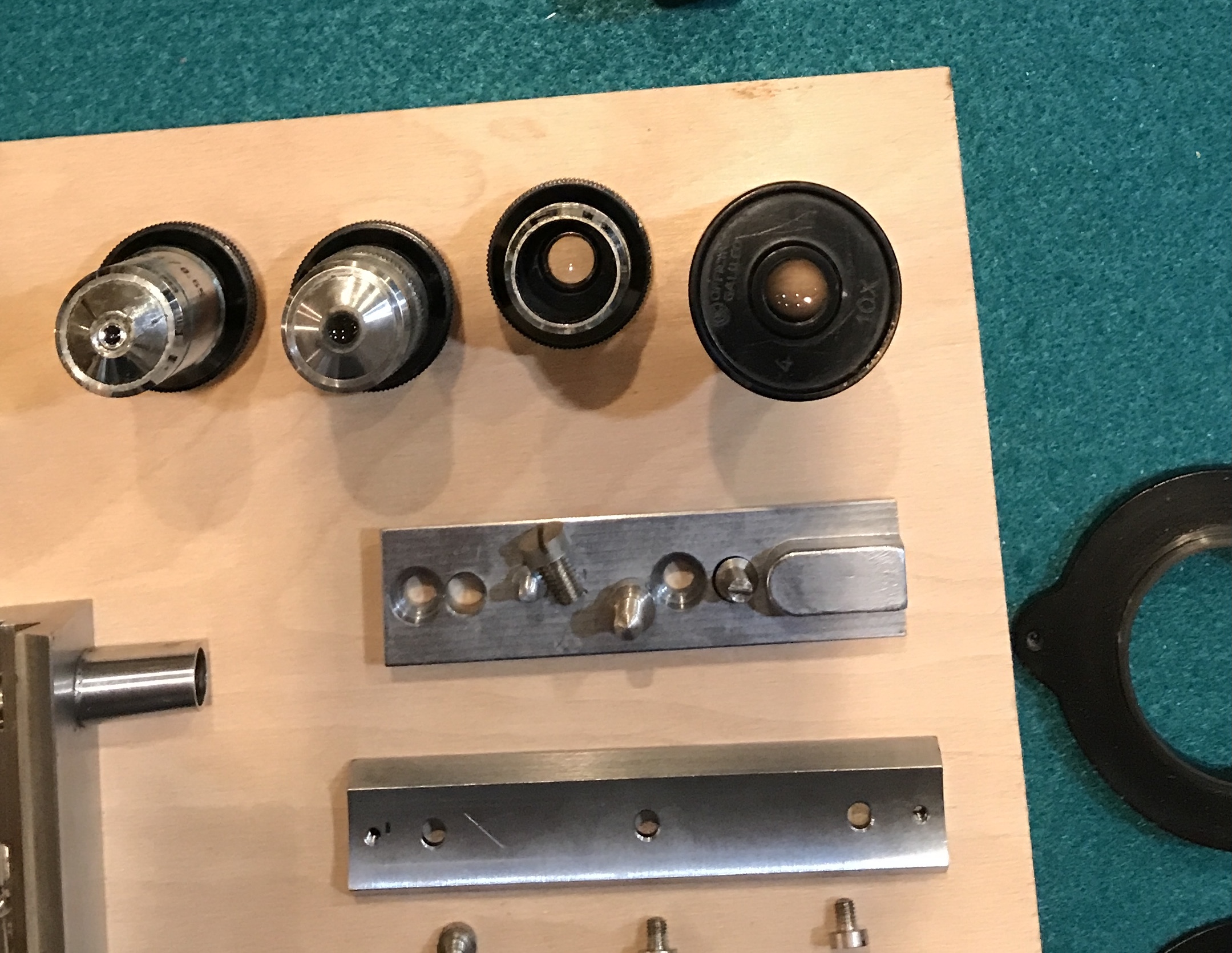
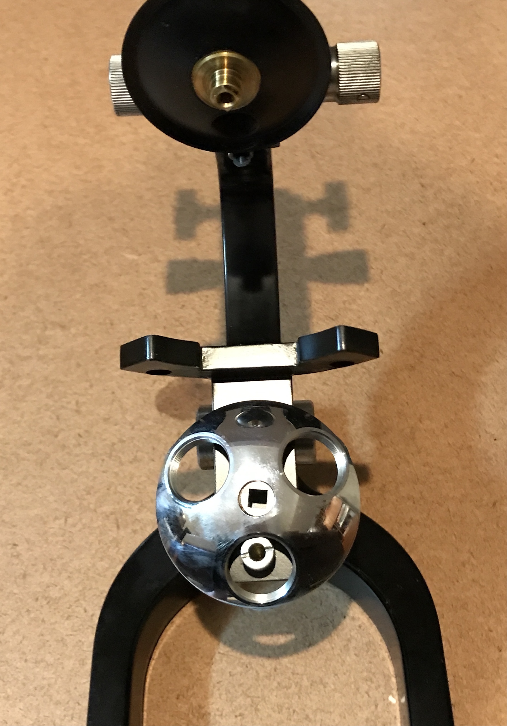
The next four photos show the three primary lenses removed and the resulting angry alien or lens holder. One screw held it in place on a square ended shaft.
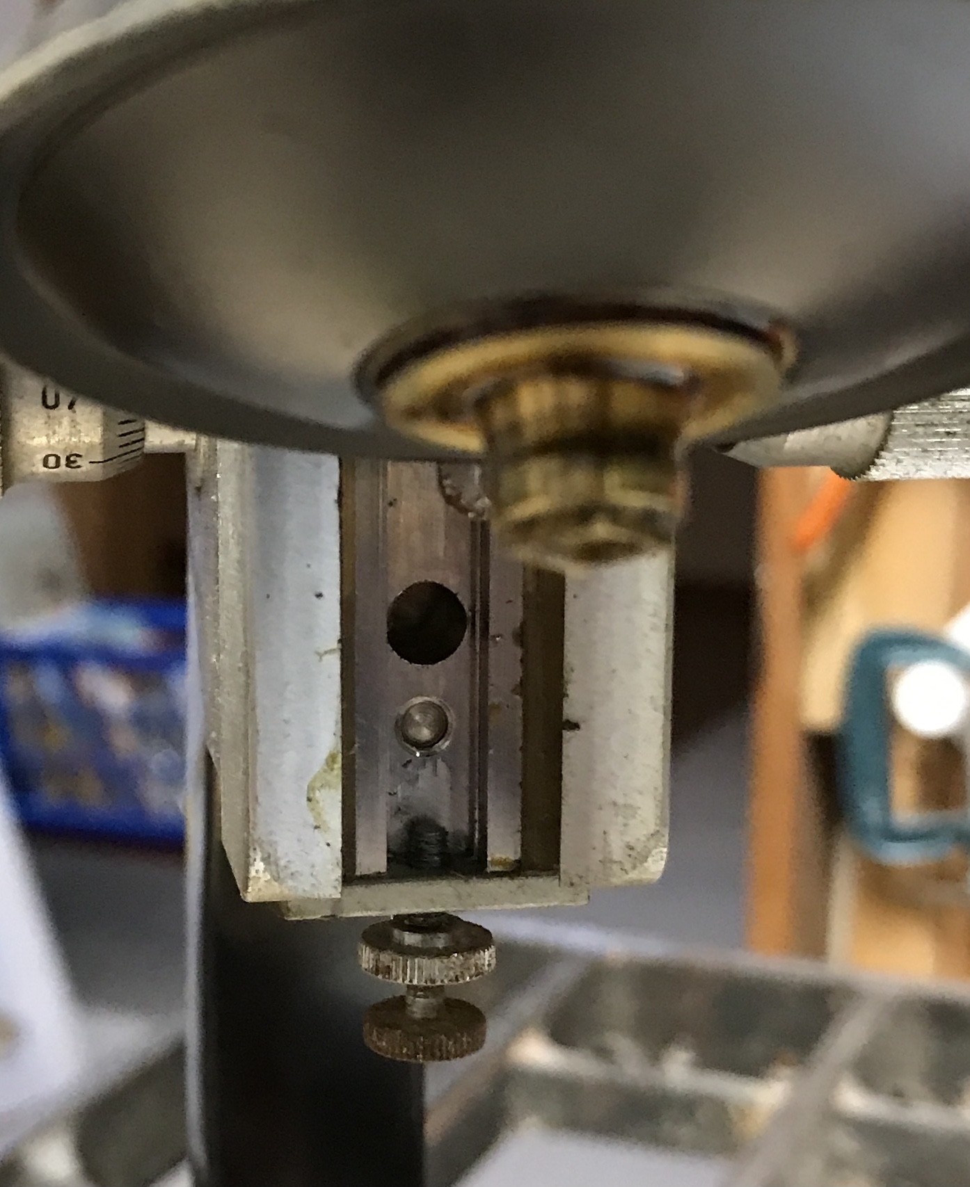
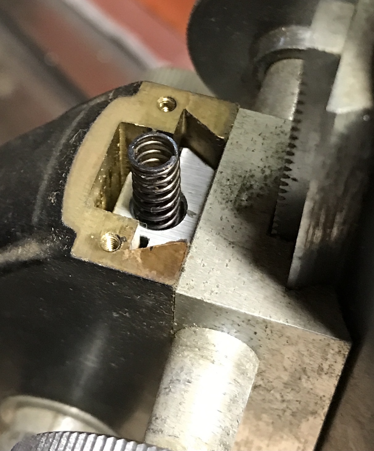
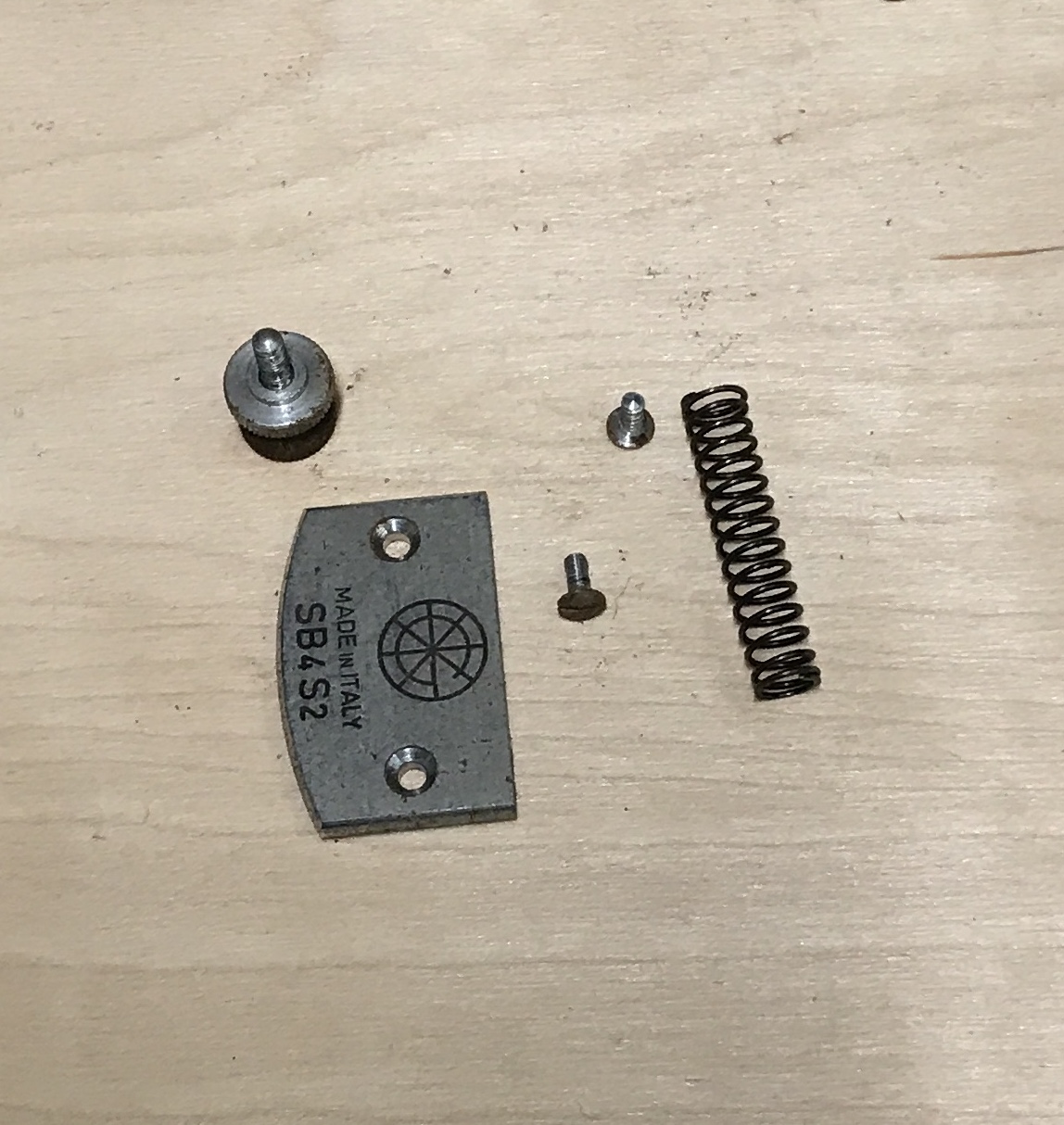
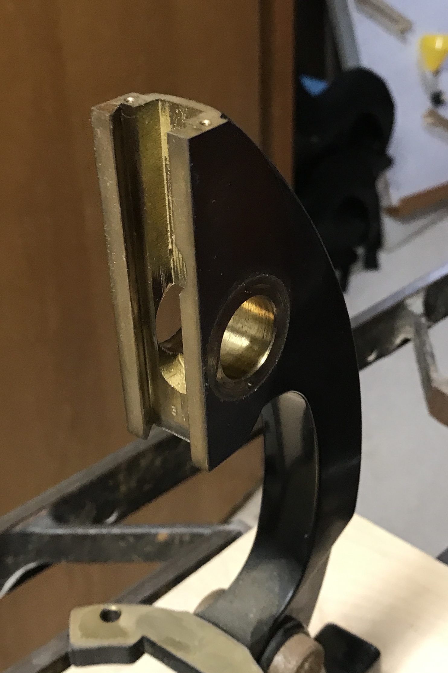
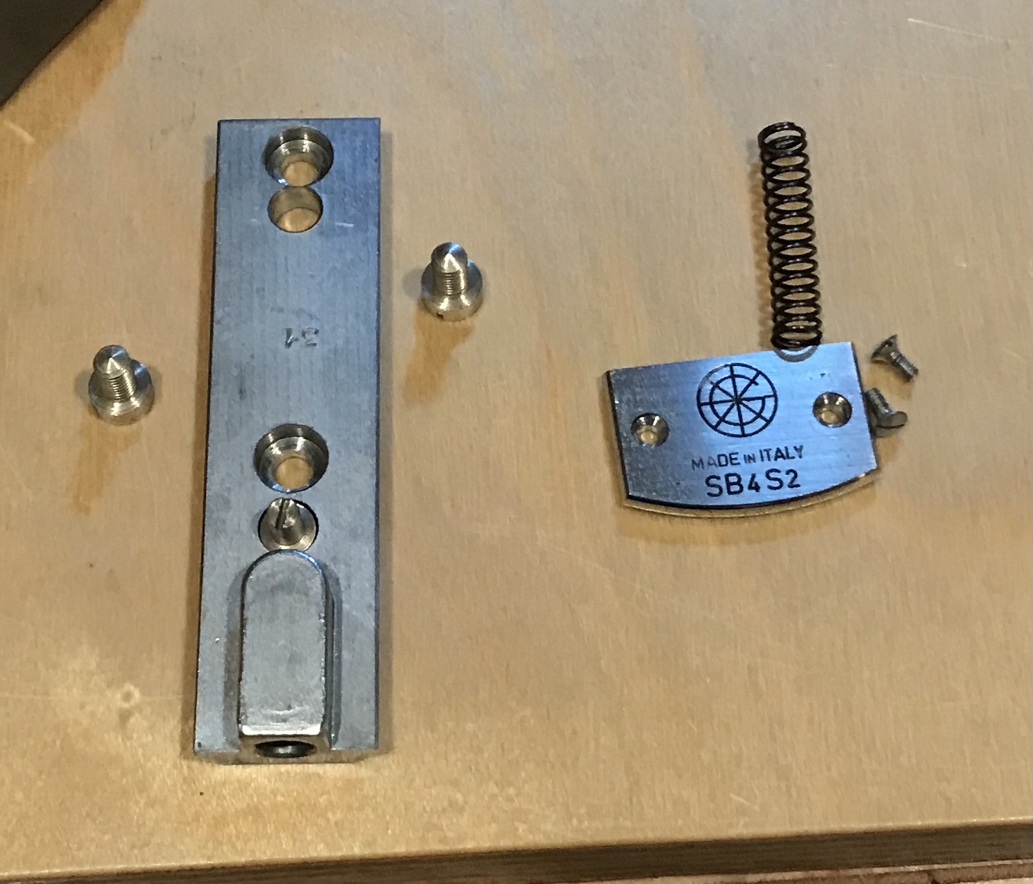
The next part removed was the top plate trapping the rack slide. It holds a spring in a hole underneath.
With the top plate removed the slide and the image tube can be slid up and off.
The next three photos show the removal of the dovetail from the image tube.
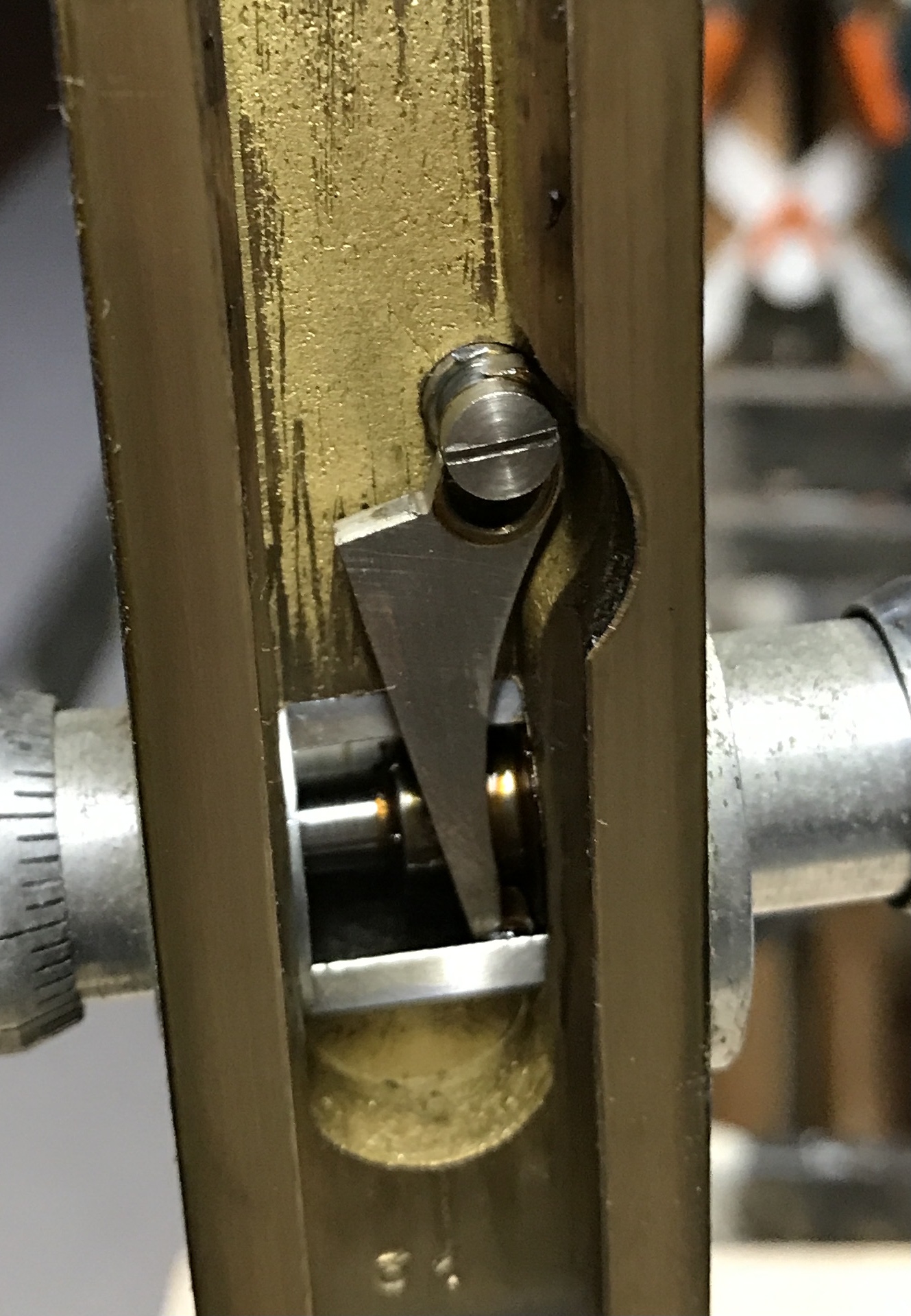
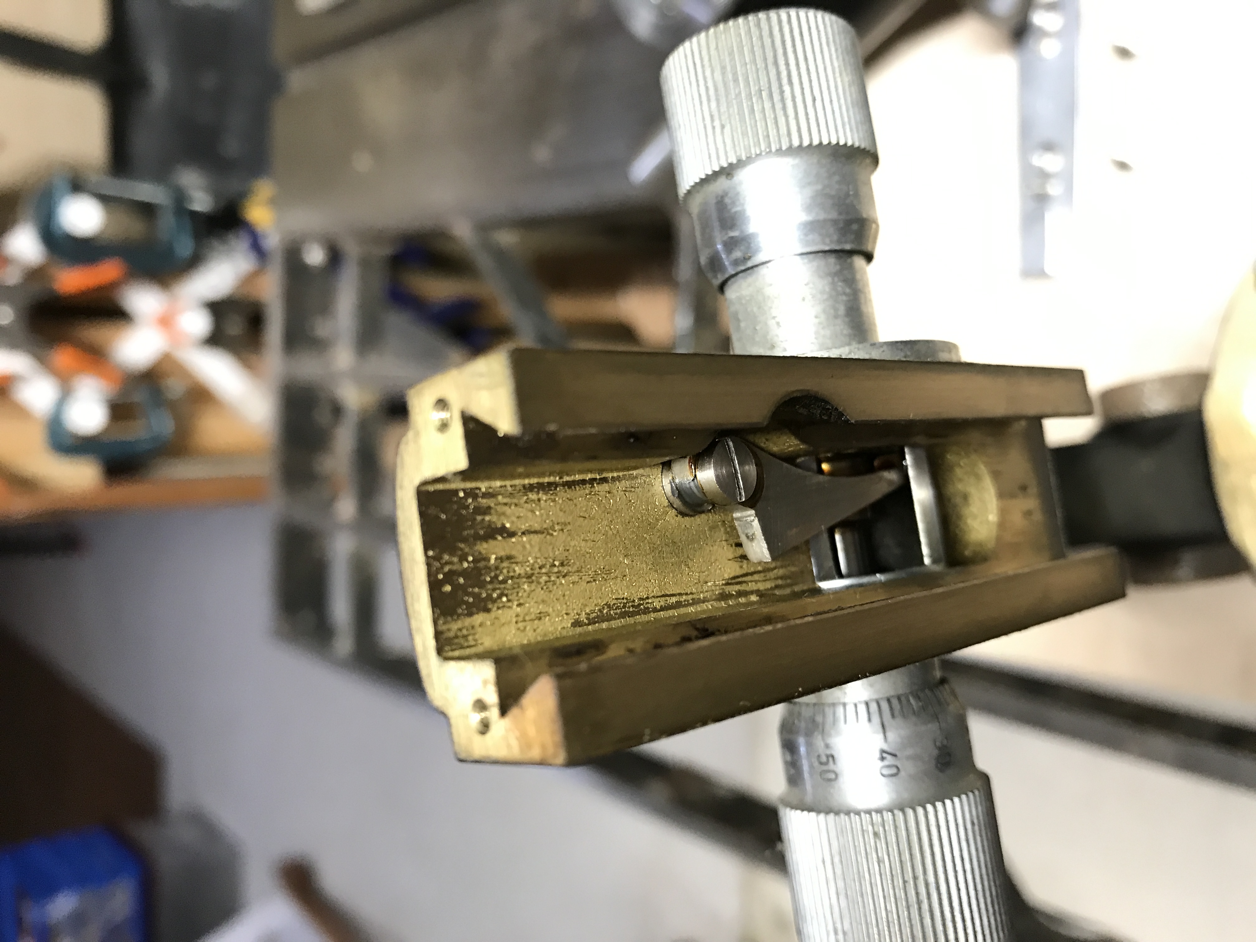
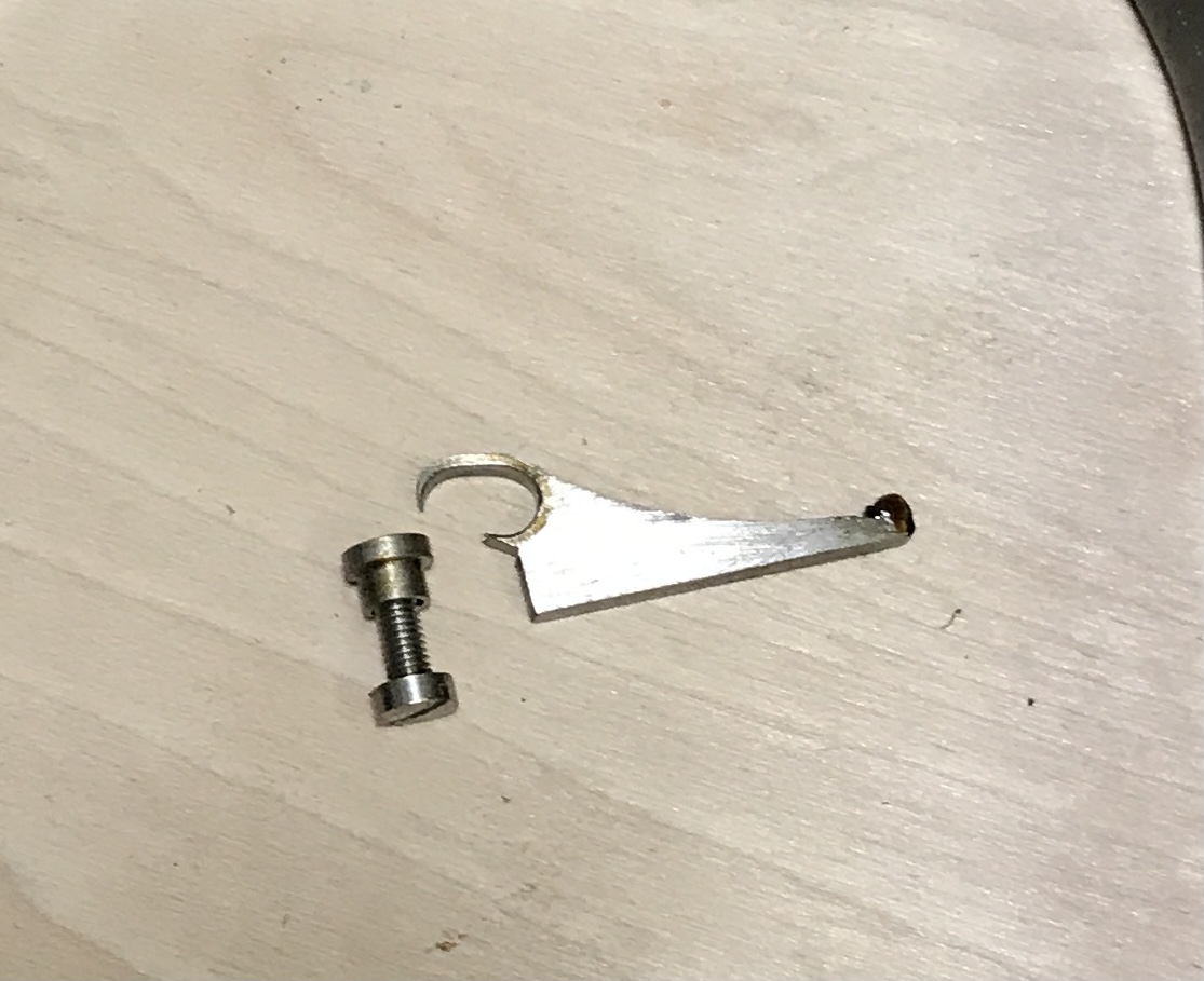
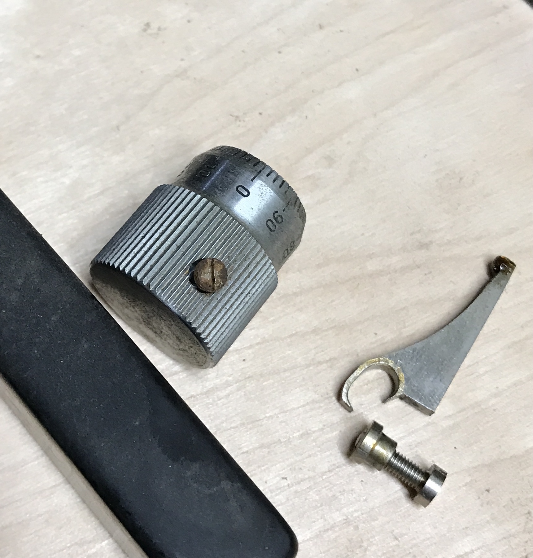
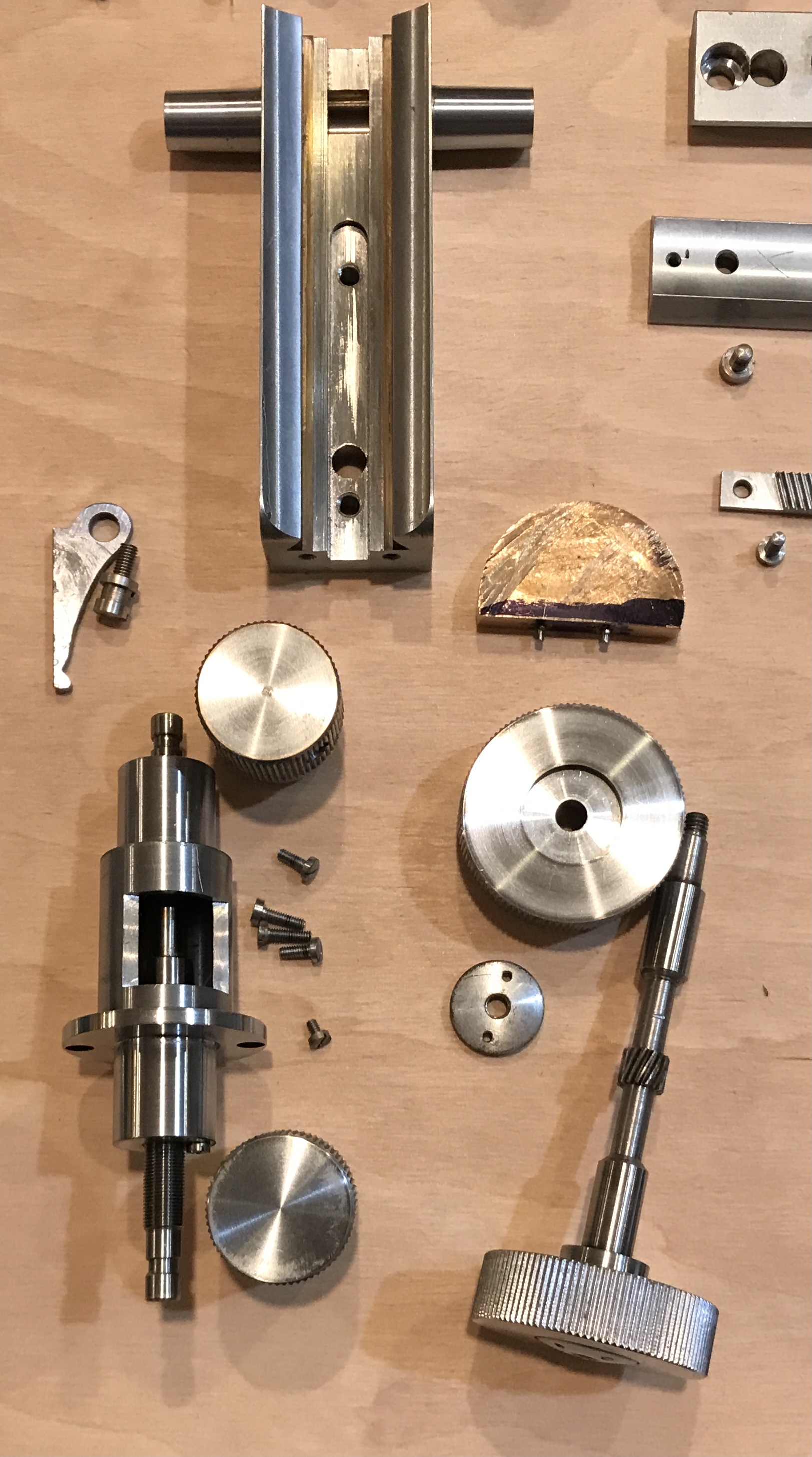
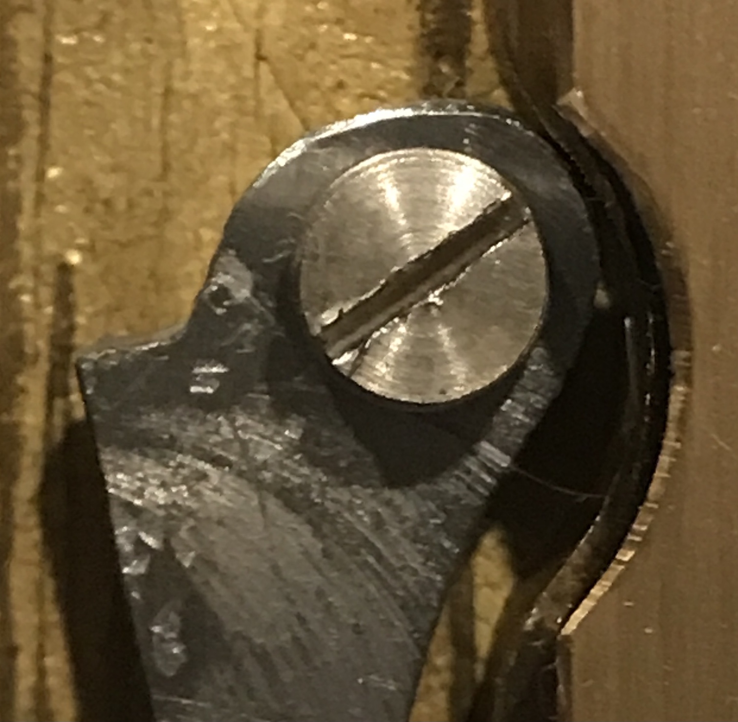
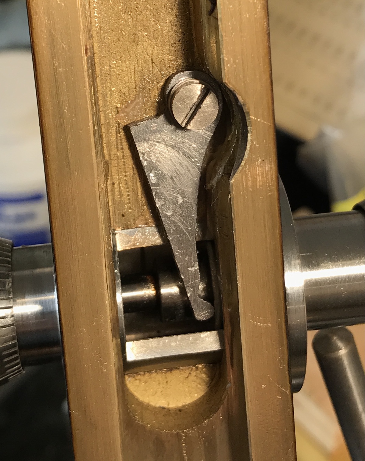
The next four pictures show the fine adjust pawl. It is broken as seen in two of the photos. The movement in the coarse adjust was tight enough that it is understandable how such a thin bit of steel would break. The screw has an odd washer.
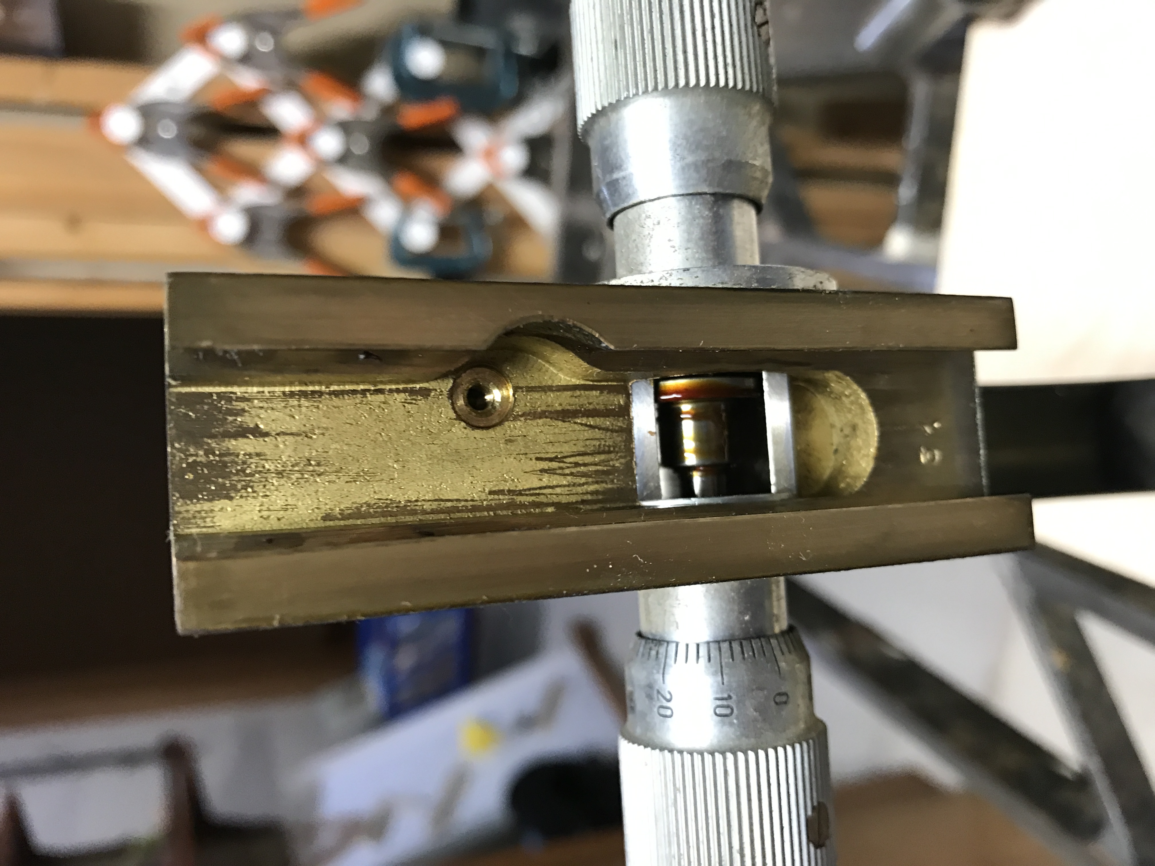
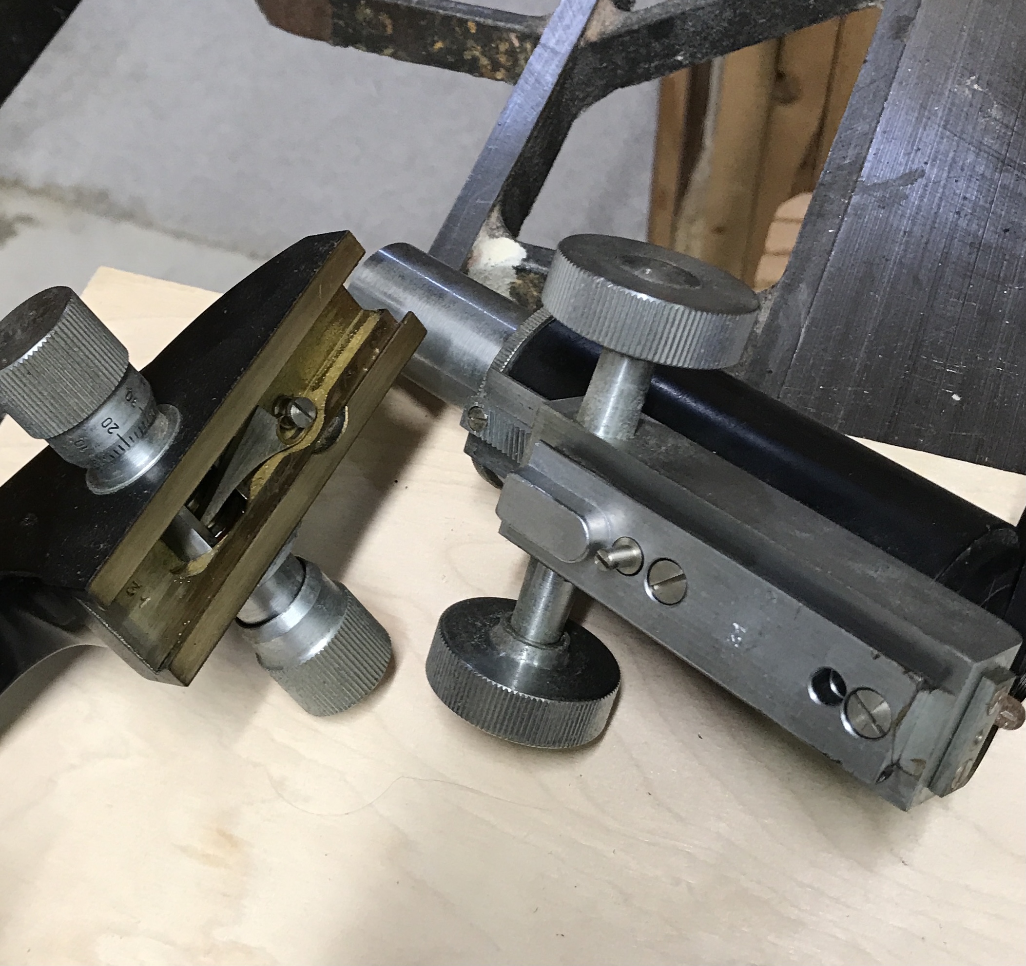
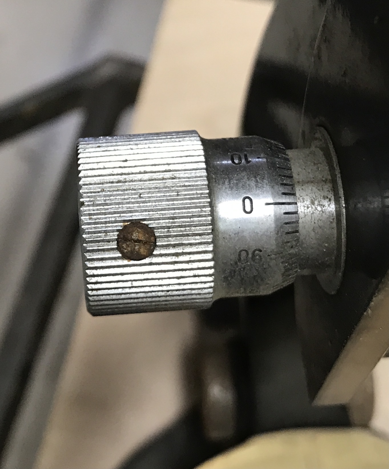
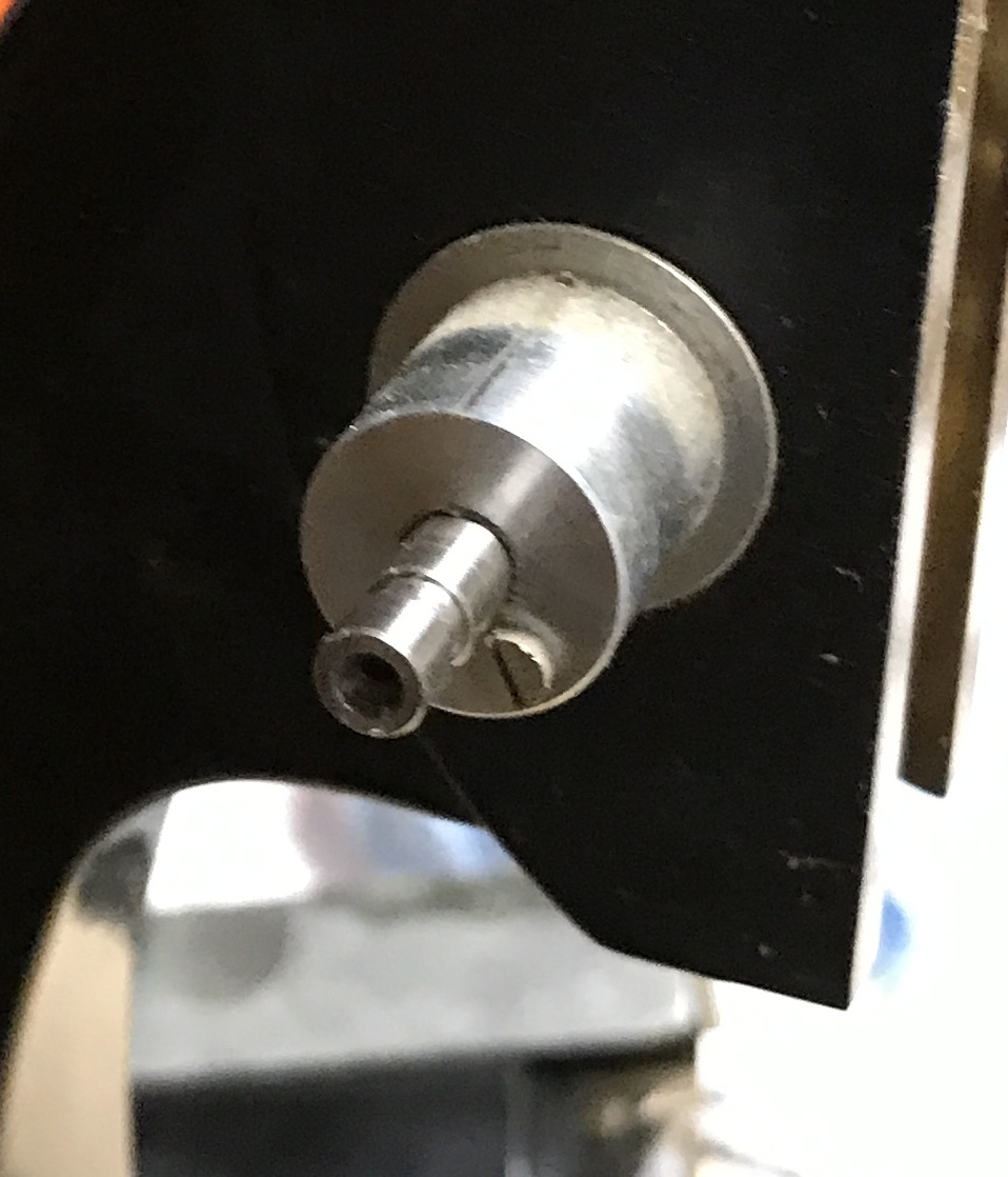
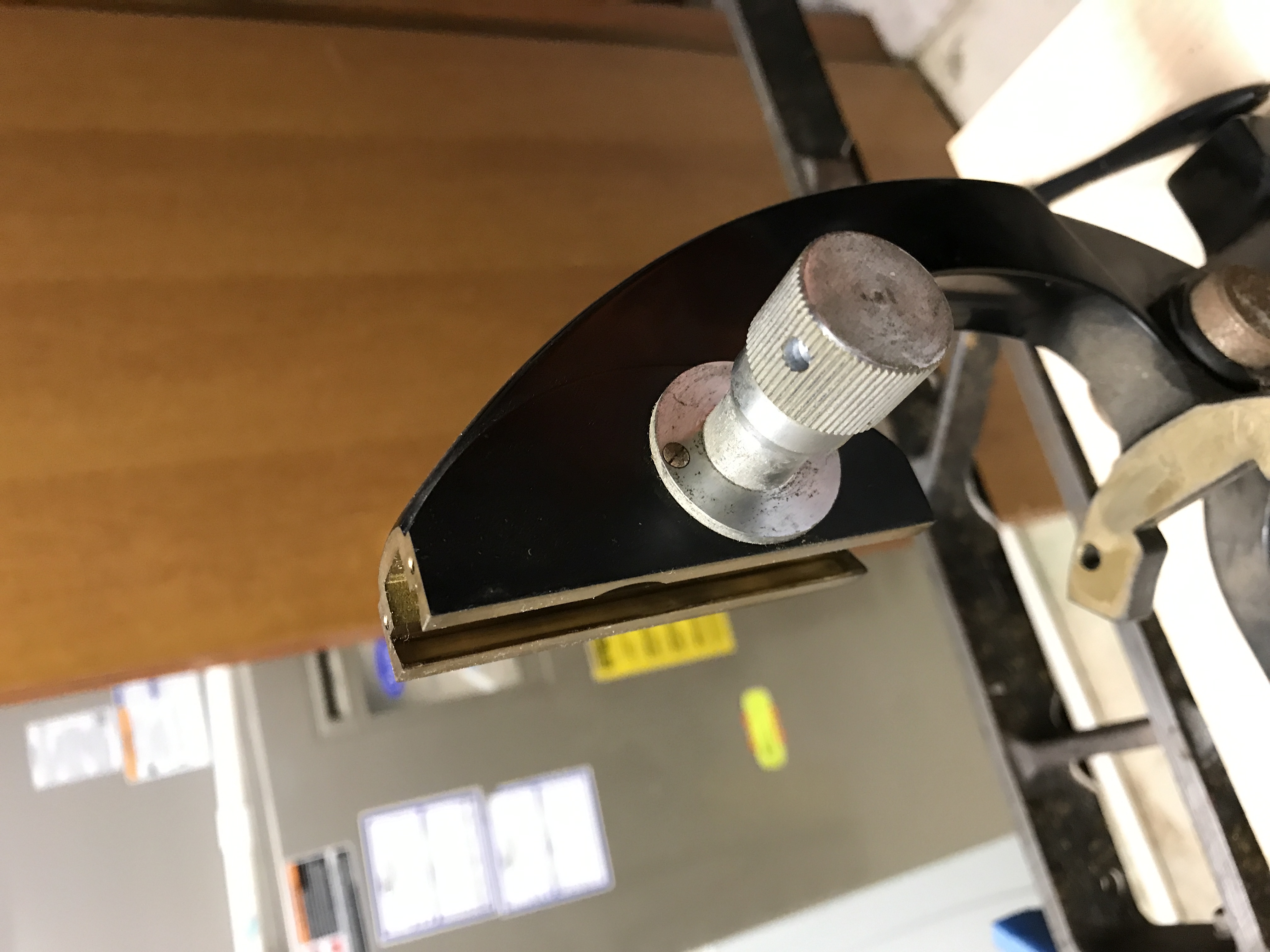
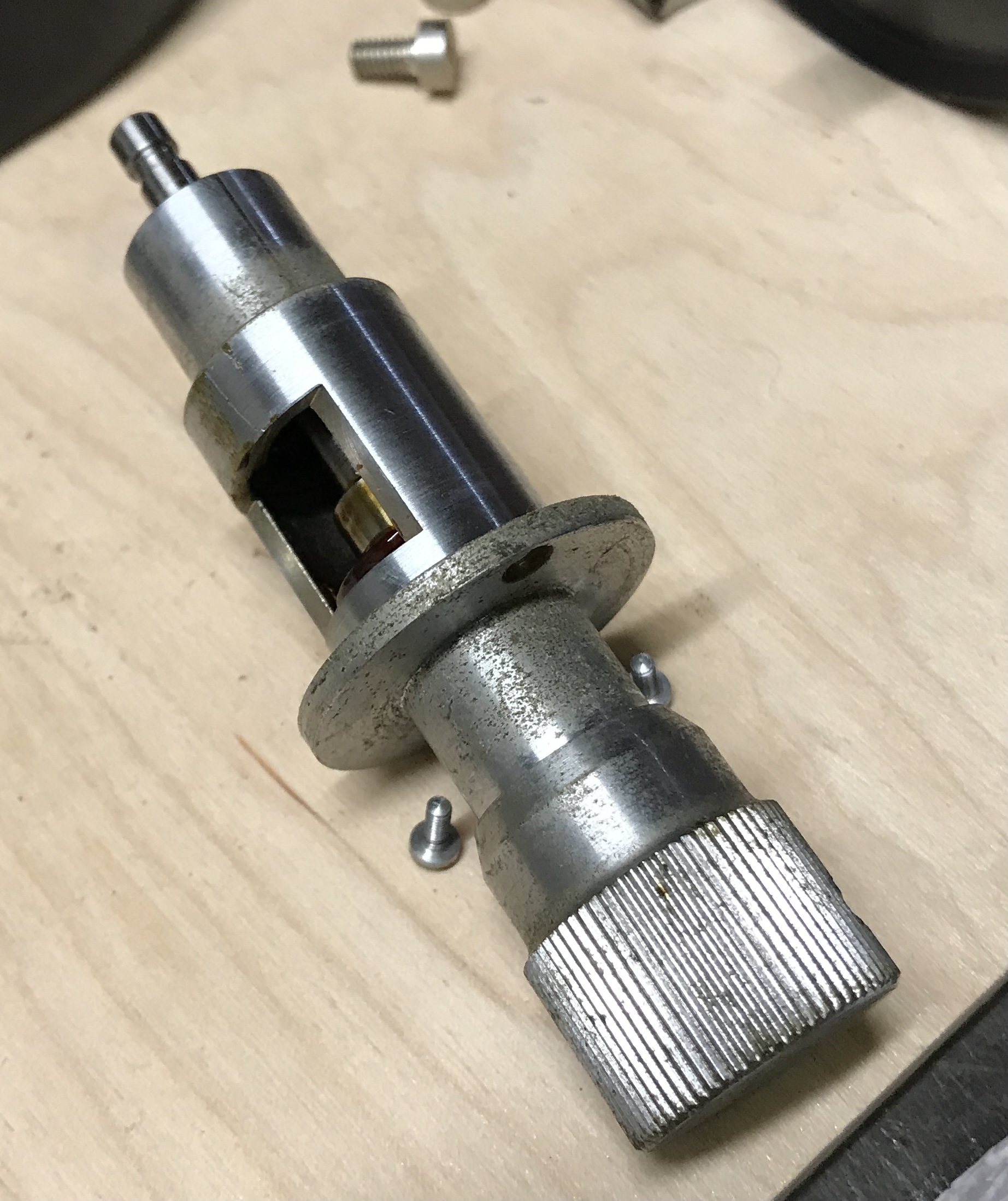
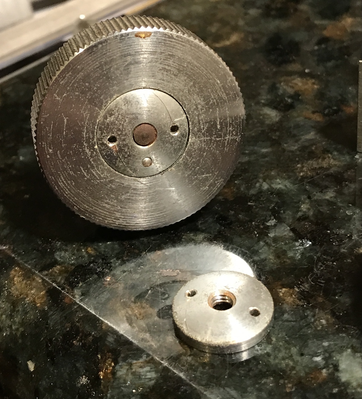
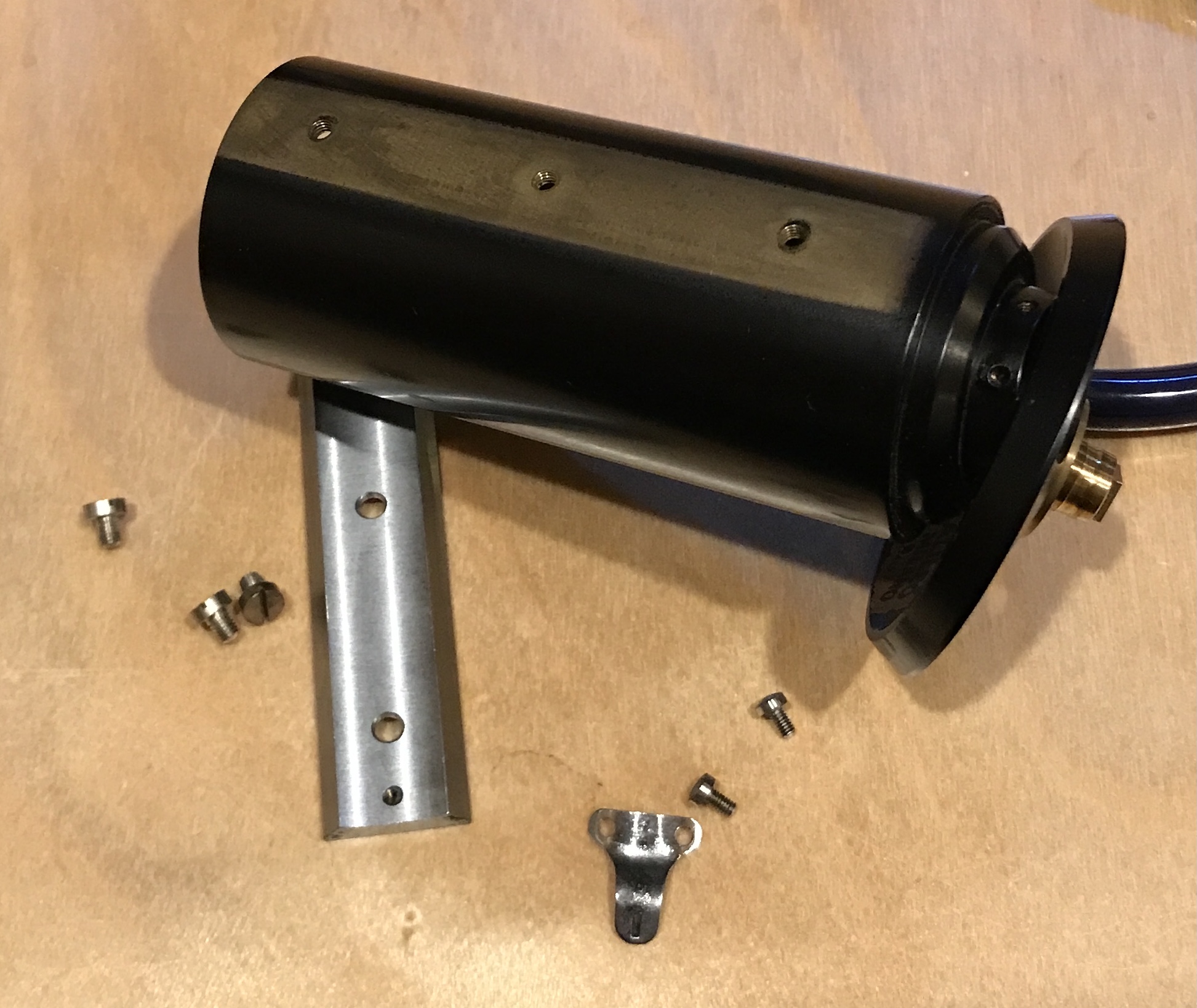
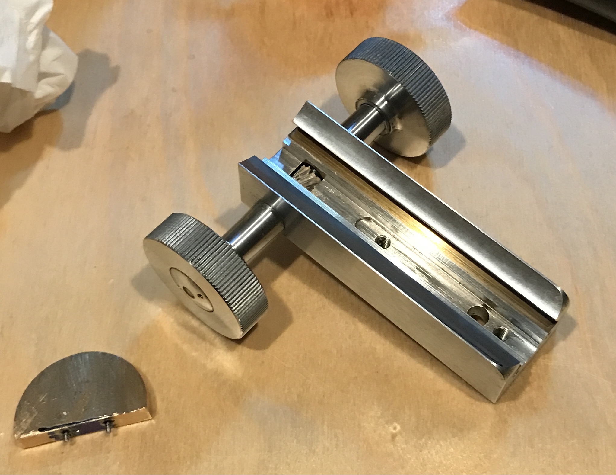
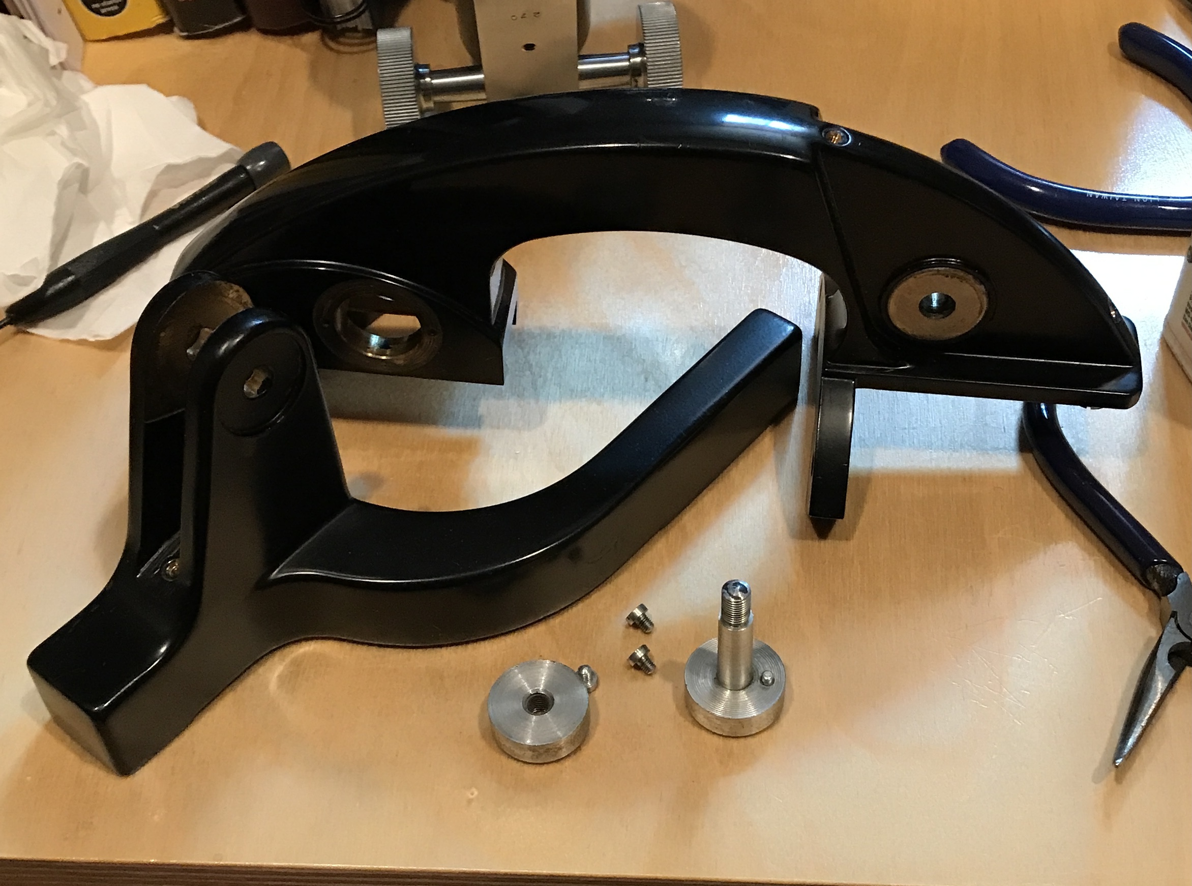
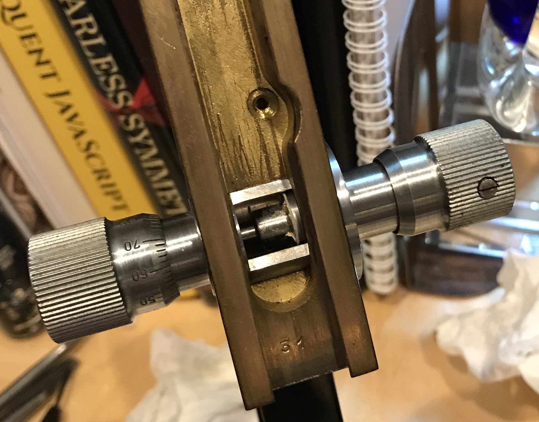
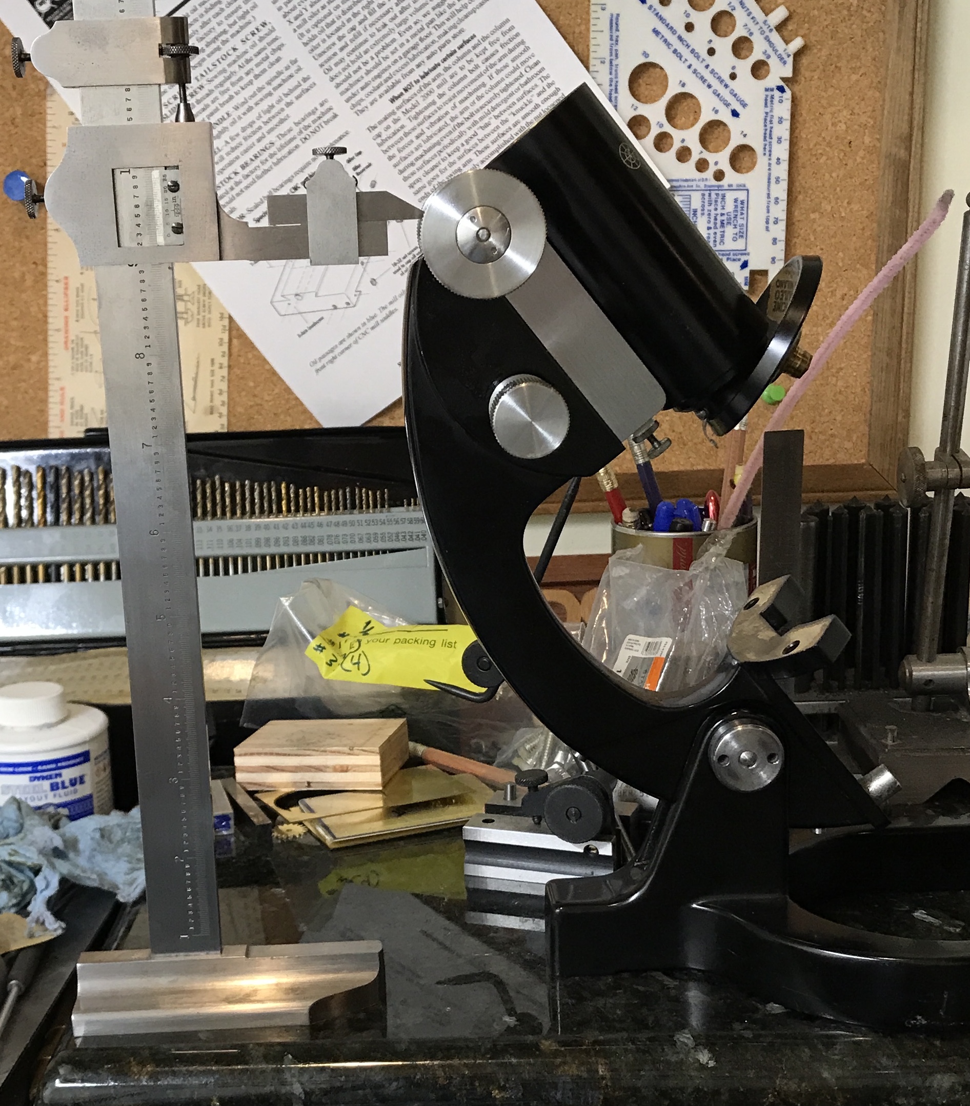
The next task was removing the fine adjust knobs from the frame. Both knobs have set screws holding them in place. One set screw was loosened and the knob removed. There is a screw in the shaft of unknown purpose. It was also removed. There are two screws holding the flange and shaft in place. Both were removed. The shaft and opposite knob slid out of the frame.
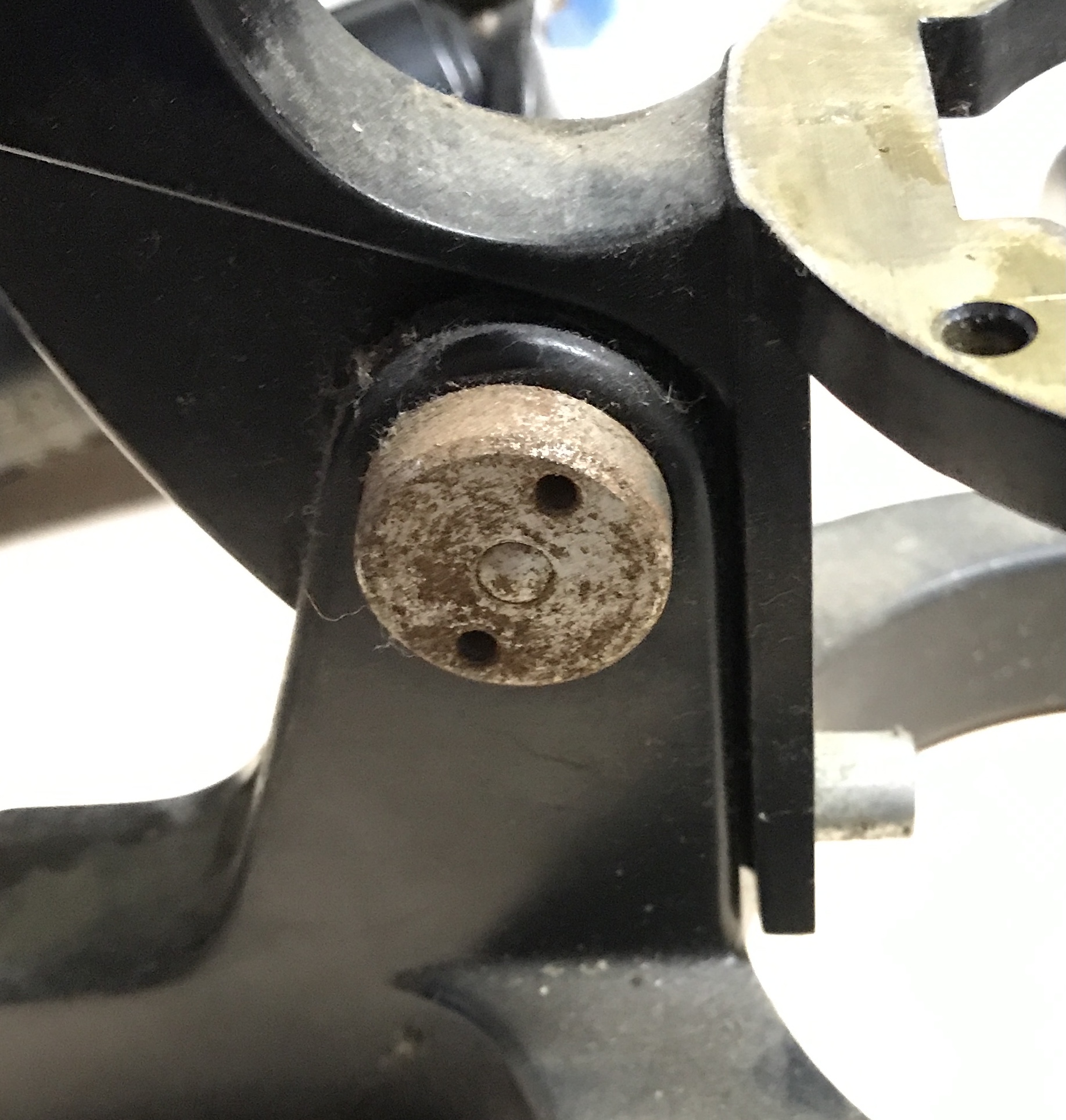
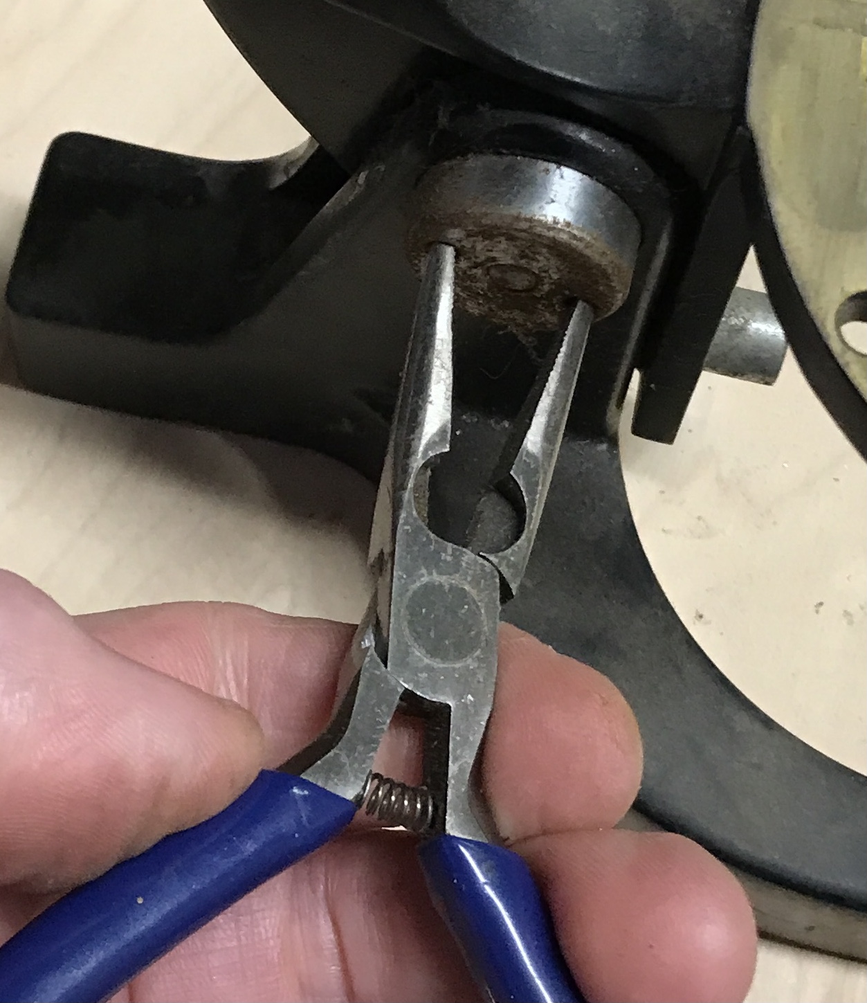
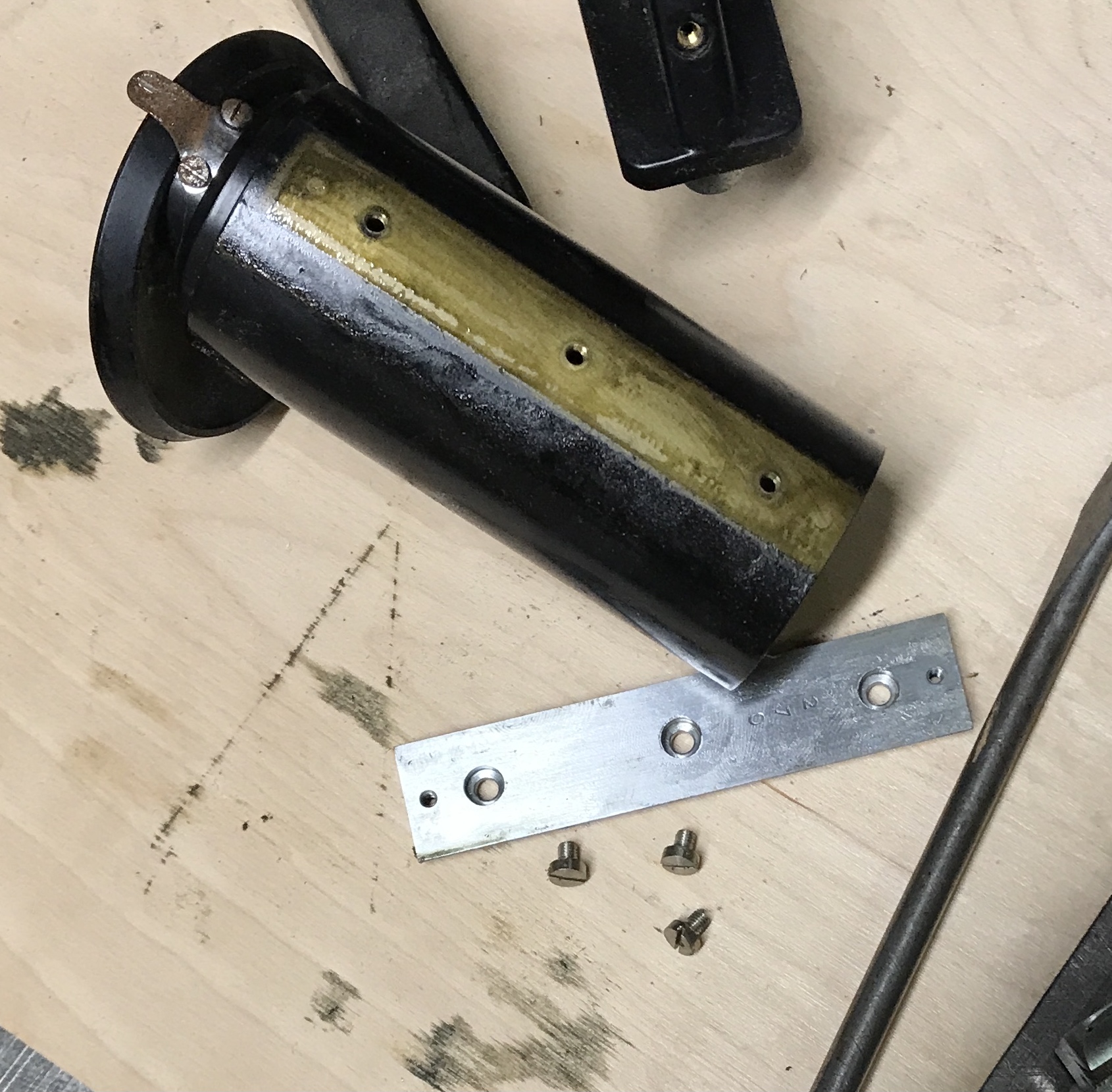
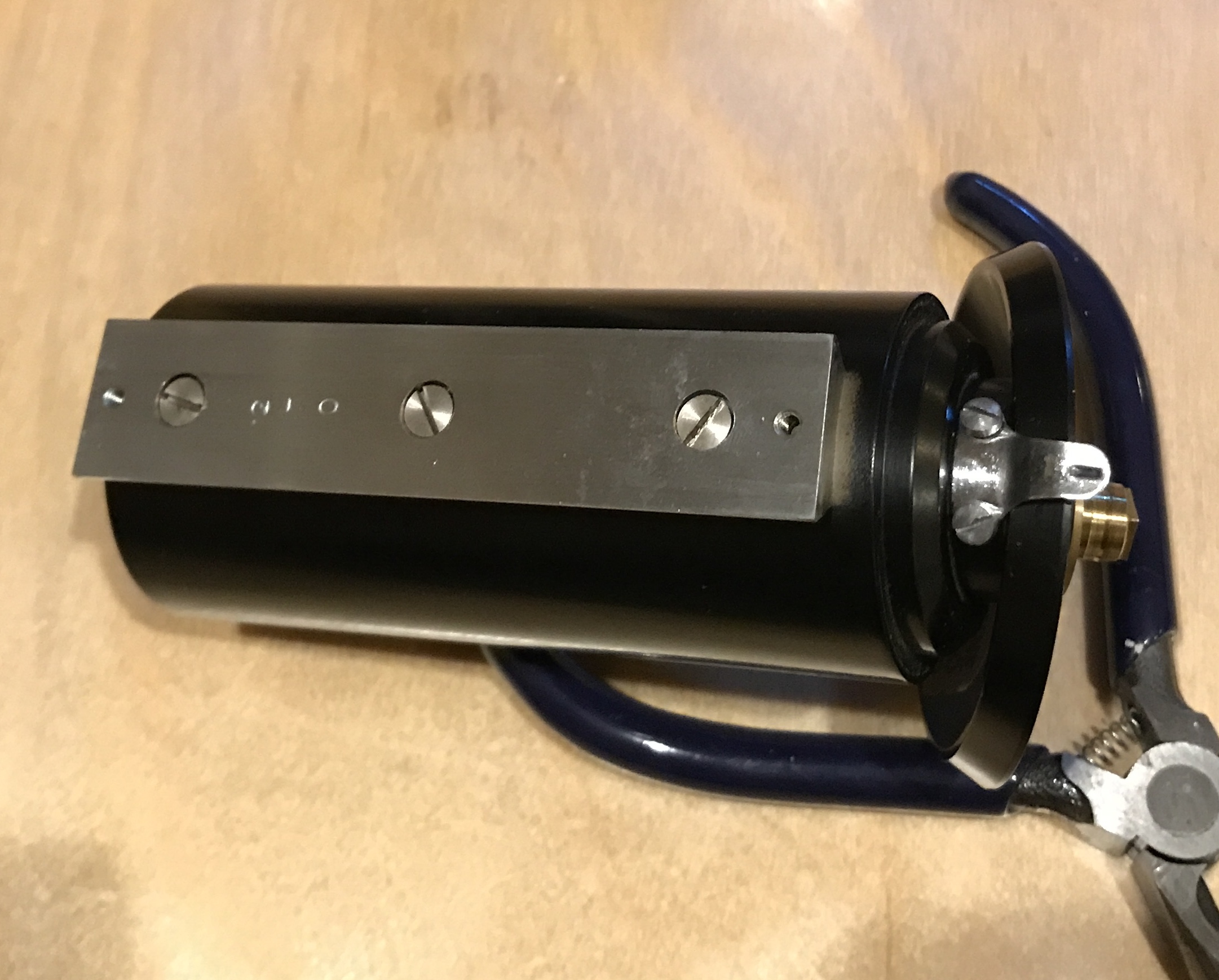
The next five photos show the separation of the frame into the base and the upper support. The nut on the end of the shaft requires a pin wrench. Luckily the holes were big enough to accept the tips of a small pair of needle nose pliers. There are a number of screws in the frame that serve no obvious purpose. They were removed.
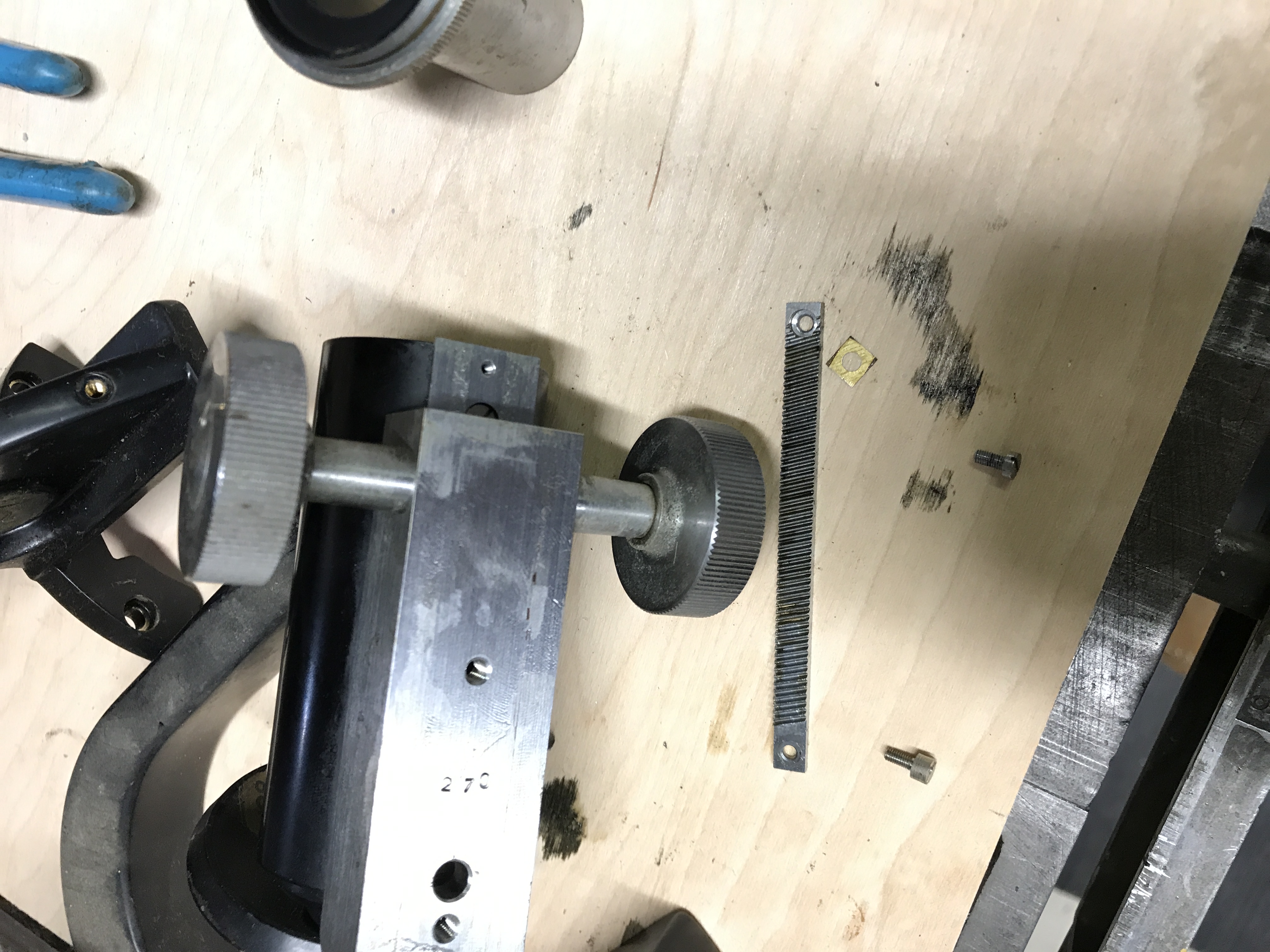
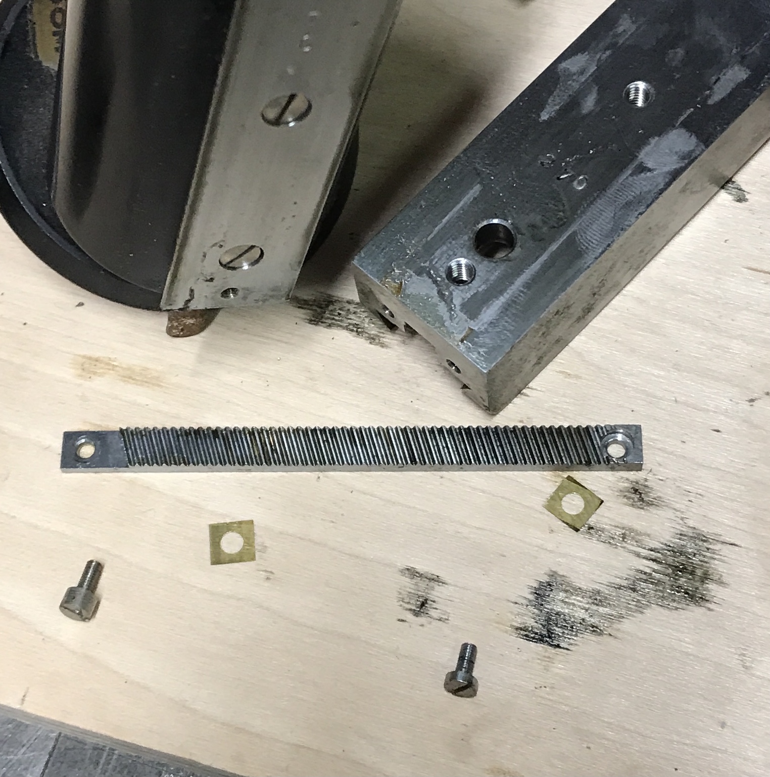
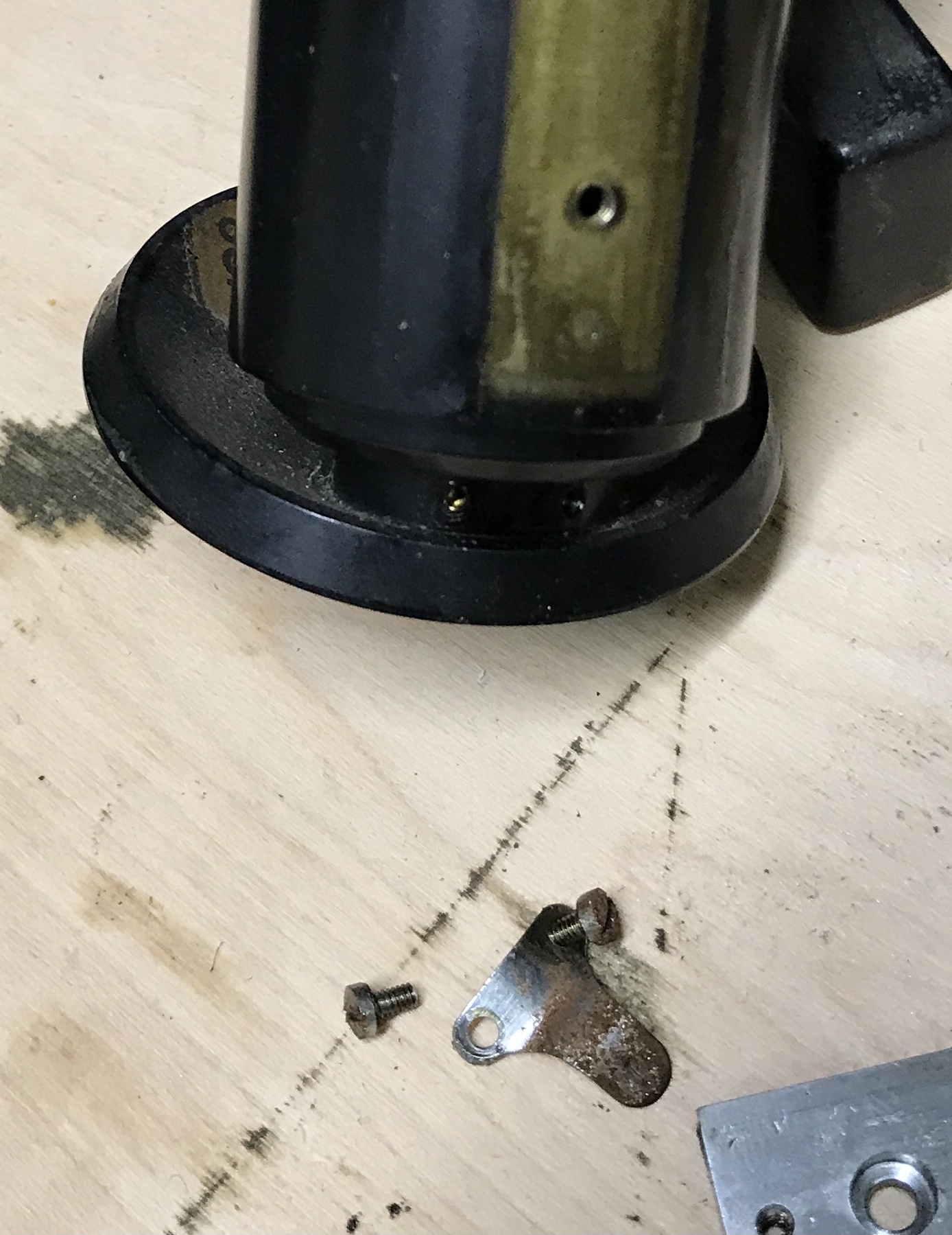
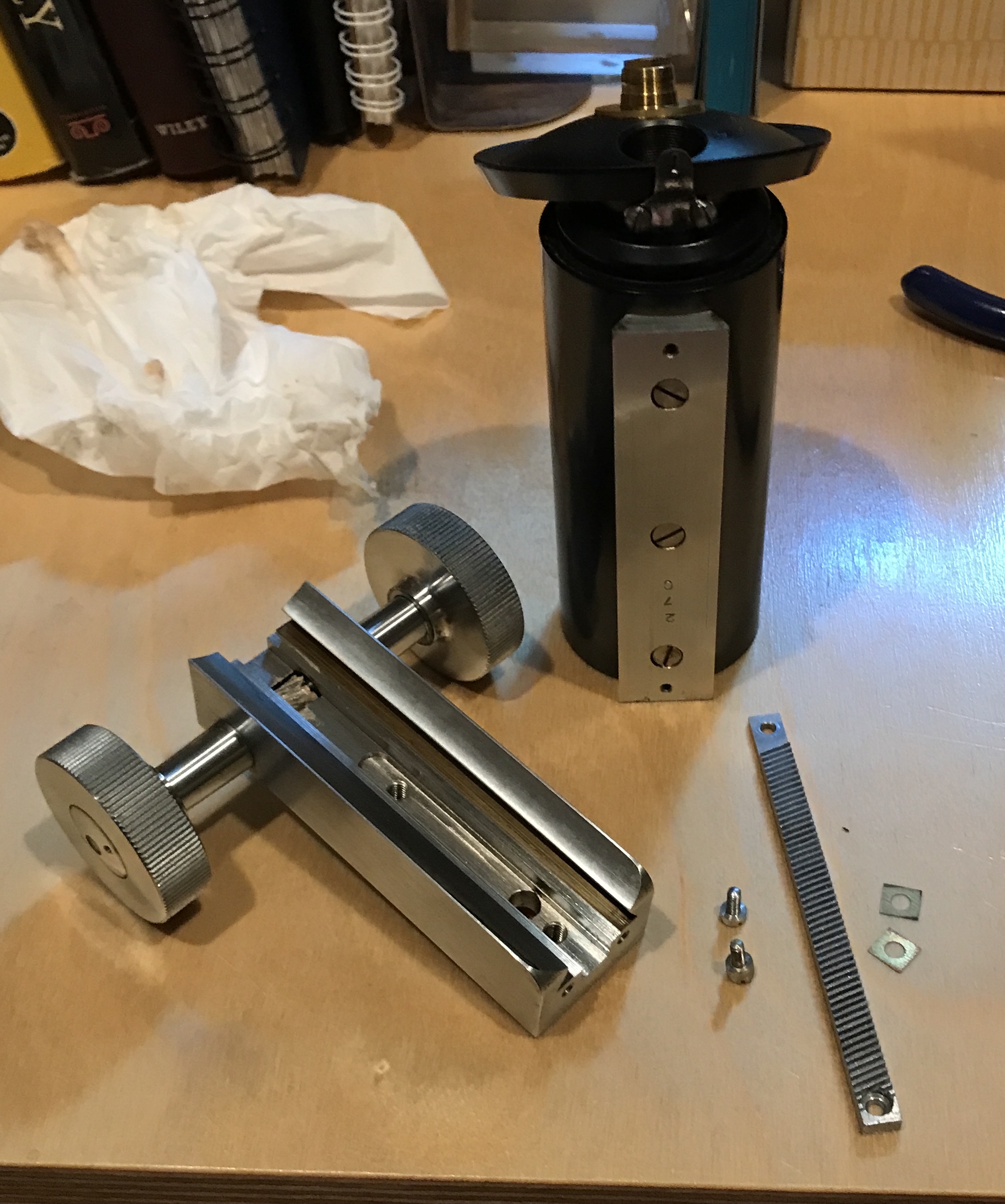
The next set of pictures shows the separation of the coarse adjustment mechanism from the image tube. At one point a hidden screw had to be removed via a provided hole. The rack is buried in this mechanism. When it came out two very thin square washers were removed from behind it.
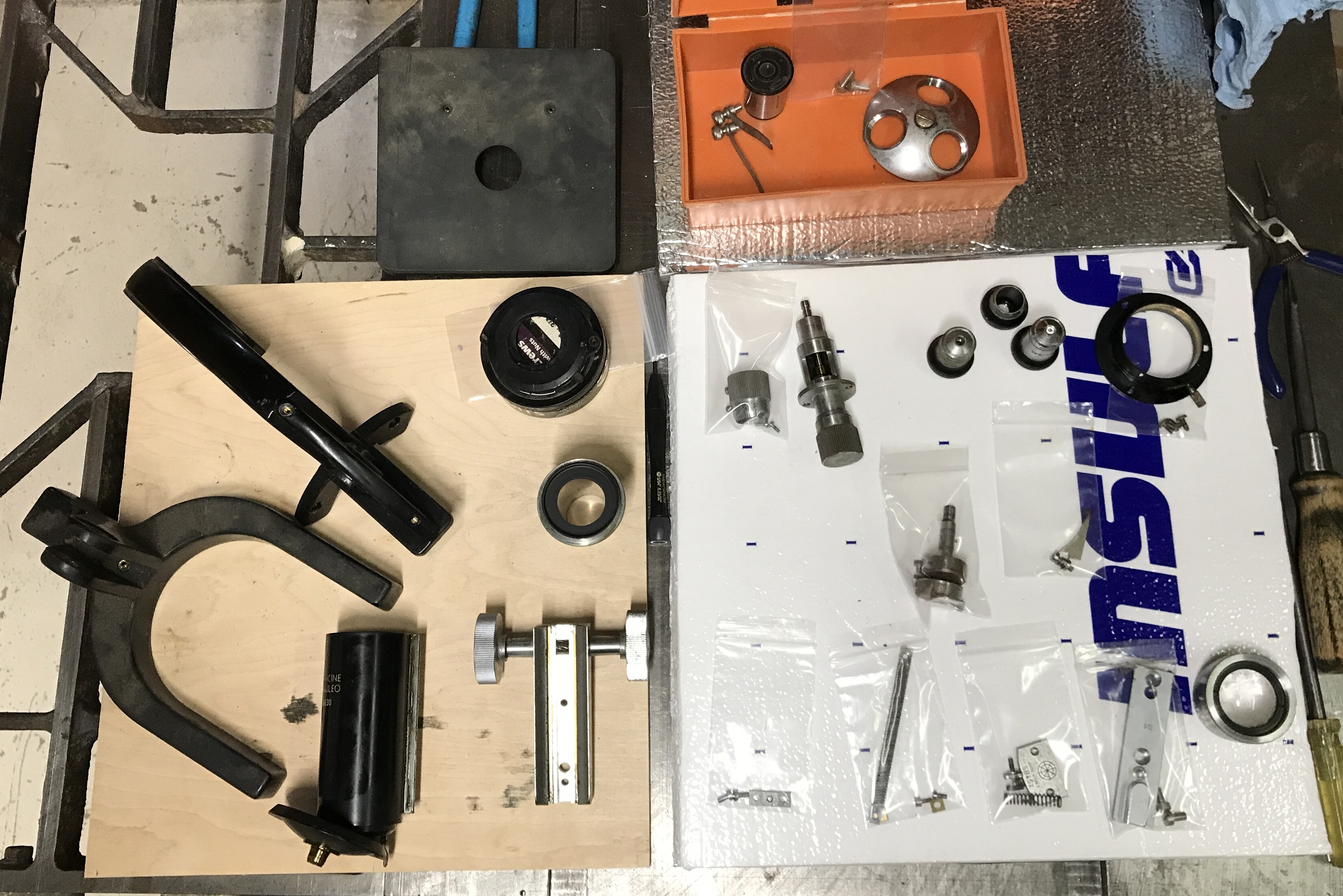
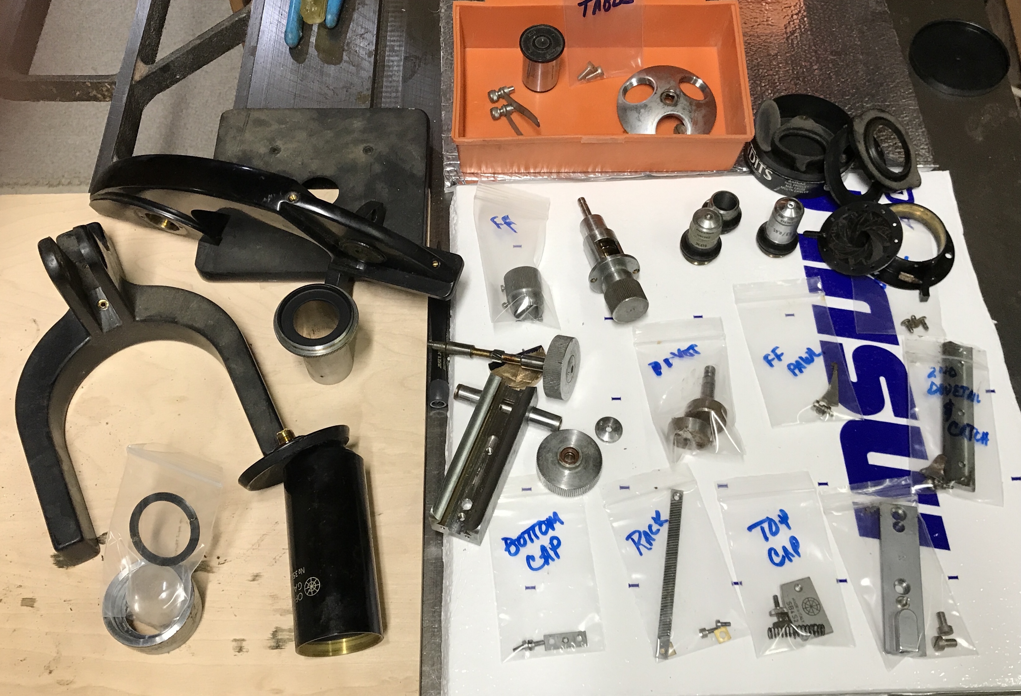
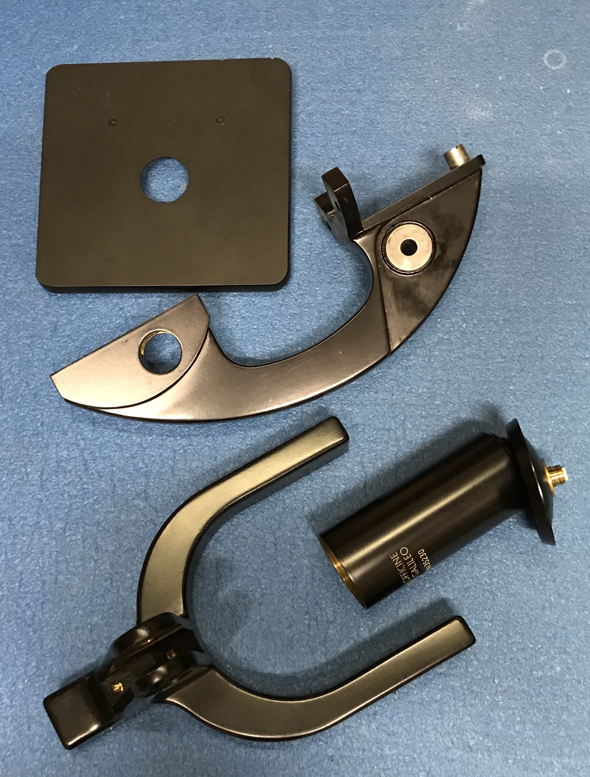
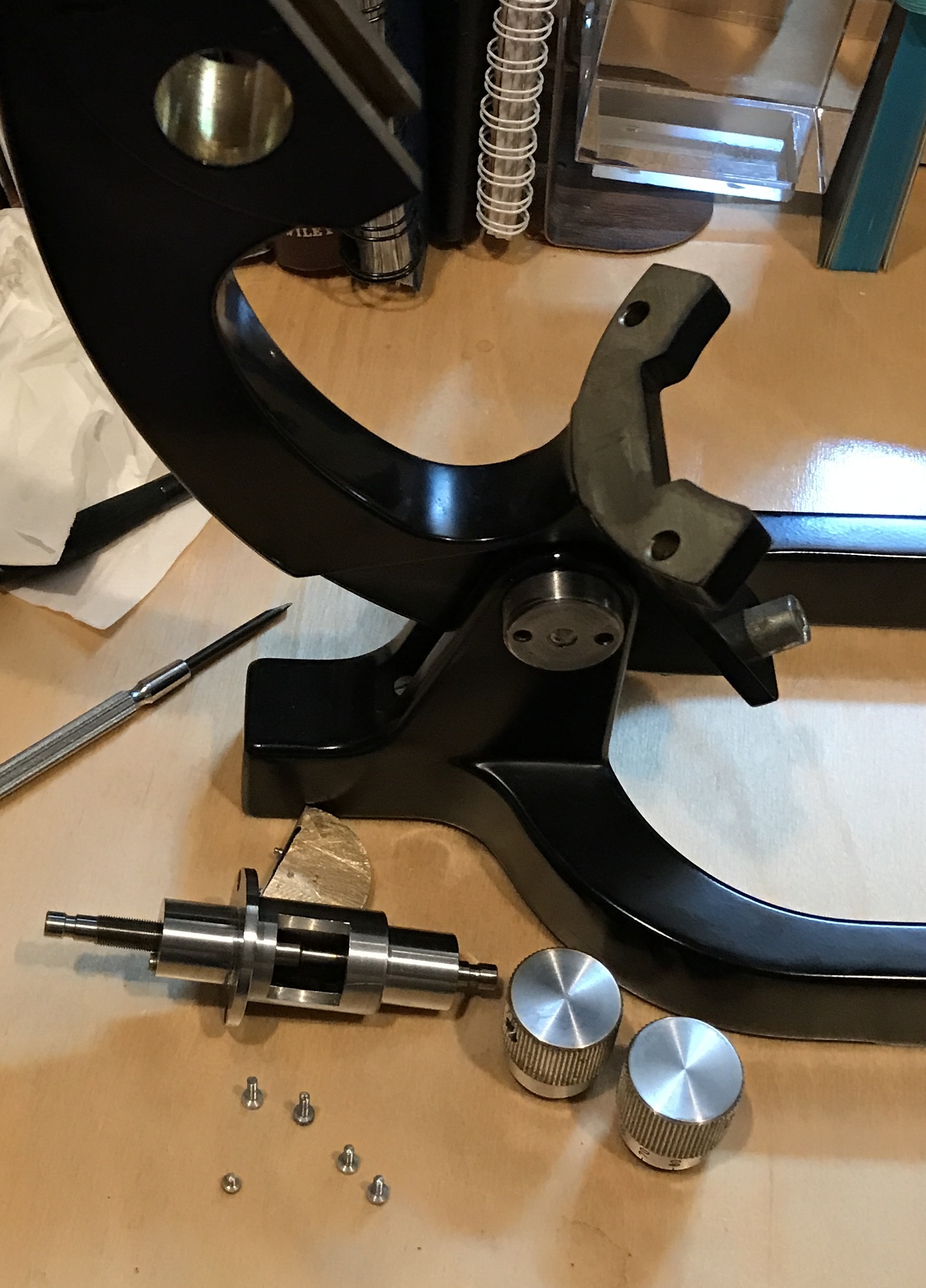
The next photo shows all of the parts at this stage of disassembly. All of the smaller parts are in plastic bags. The bags were labeled after this photo was taken. The parts are packaged by subassembly.
Three things need further disassembly: the coarse and fine adjust mechanisms and the diaphragm. The coarse knobs are held on by screws that use a two pin key. This needs to be made. A new pawl needs to be made.
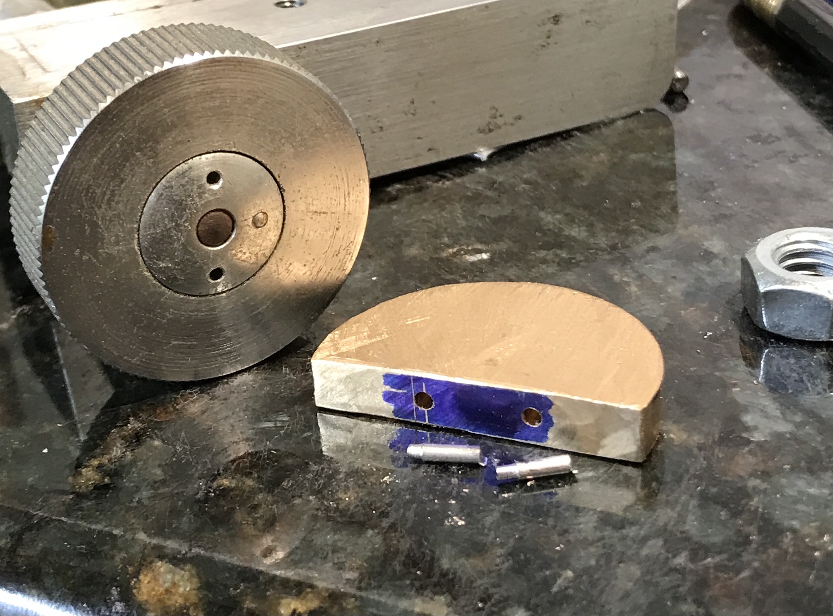
The pin wrench will be made from a scrap of 1/4" brass. The brass scrap is half a disk from 1 1/4" round stock. The flat end was milled smooth. The two pins need to be about 3/8" apart. The stock was marked at 7/16" from the edge and centered on the 0.225" thick part. A number of drills were inserted into the holes. The holes are approximately 0.054" in diameter. I have a broken drill that is 0.046" in diameter. It is too wobbly in the hole.
Decided to make two pins. A length of 1/16" steel was held in the chuck with about 1/4" protruding. The tip was reduced to 0.05" in one 0.005" pass. There was a lot of chatter, but the tip was cut for a length of 3/32". The end was cut off at about 1/4" with a hacksaw. This was repeated to make the second shaft. The reduced ends fit nicely within the holes. The piece of brass from above was drilled about 3/8" in from one end and centered across the 0.225" width. The holes in the coarse adjustment screw were measured. The outside measurement is 0.45" and the inside is 0.35". The second hole was drilled 0.40" from the first.
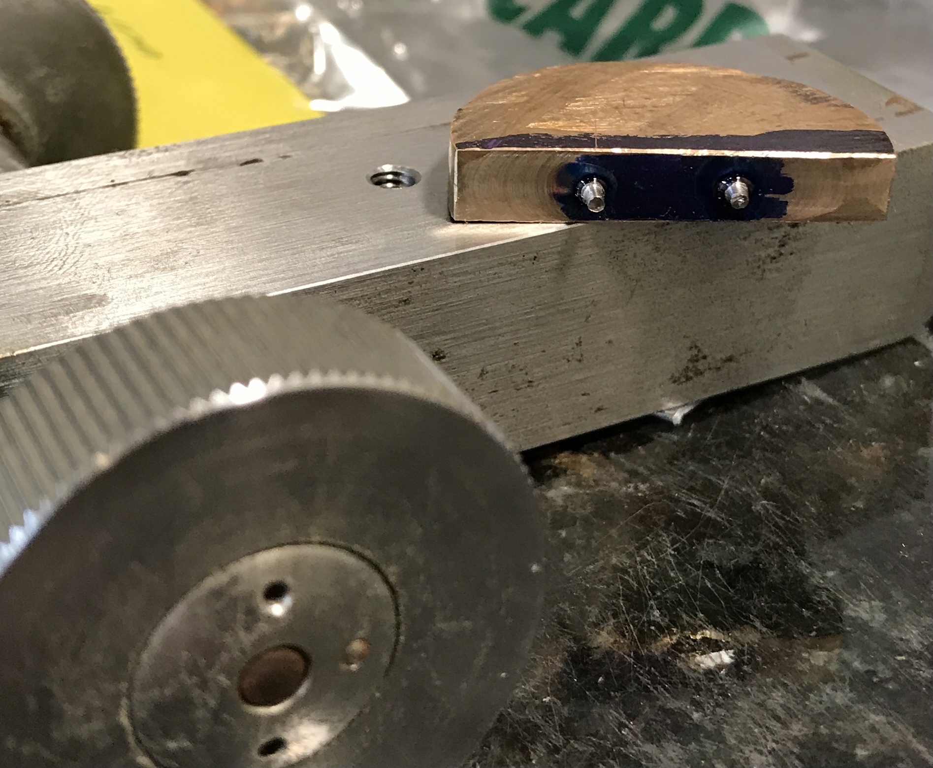
A drop of Loctite red was put into each hole. The pins were put into place and aligned with a straightedge. This Loctite sets in 20 minutes, but takes a day to fully cure.
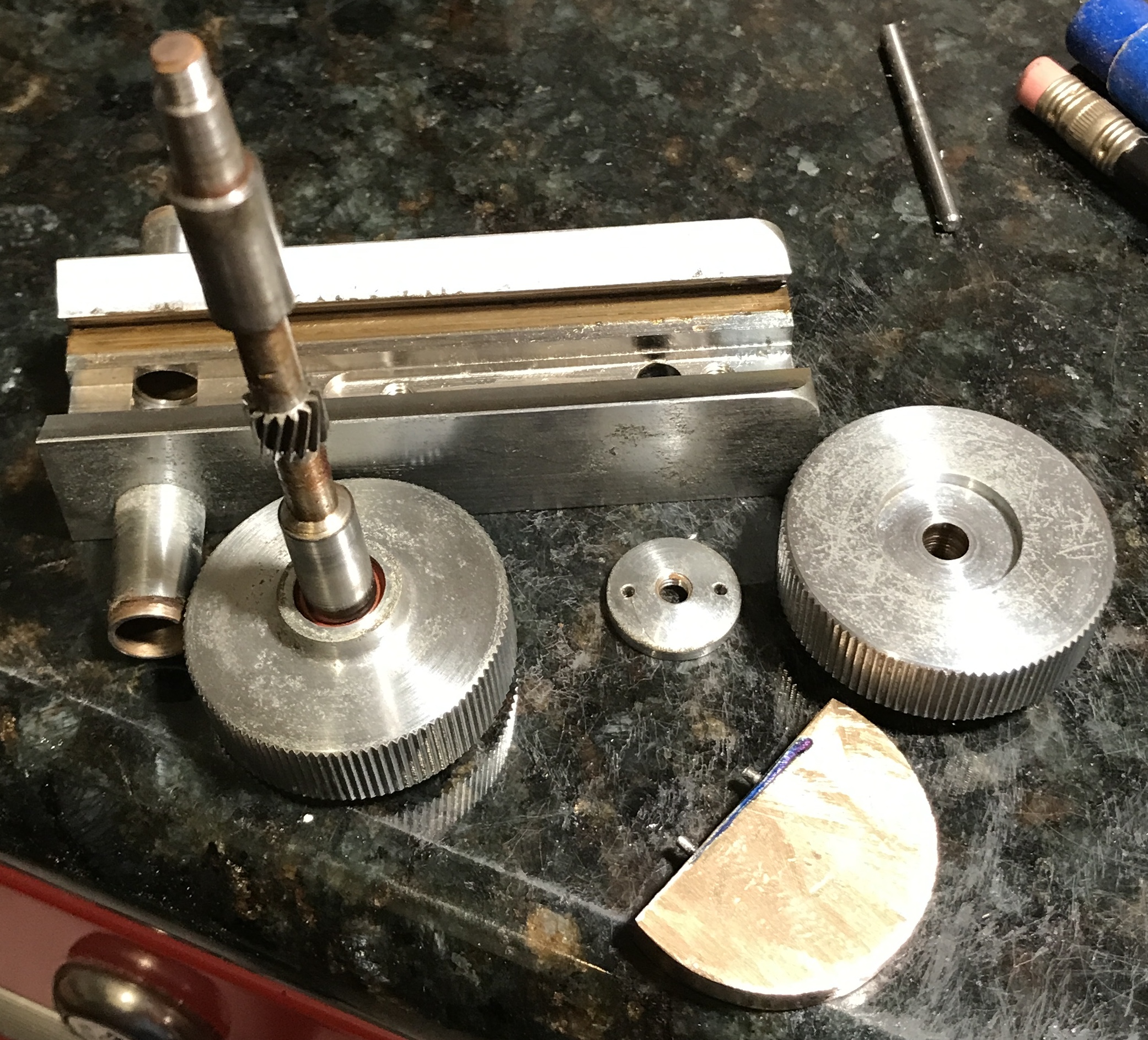
The pin screwdriver was put to use this morning. The pins were a fraction too far apart. With a little work I was still able to use it to remove the screw cap from the handle. The disassembled fine adjust handle is shown below. The opposite handle could not be removed. There is a pin holding this screw cap in place. I don't want to drill the pin out, so this handle won't be removed.
A second dovetail was still attached to the optical tube. Its three screws were removed. It readily separated from the tube. This is shown in the first photo below. The viewing tube also has a catch screwed to the lens selector. This was removed via two small screws.
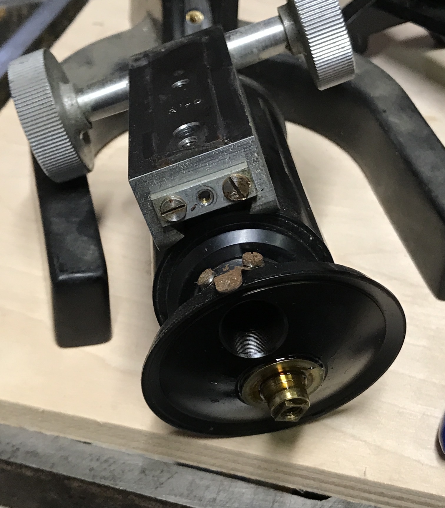
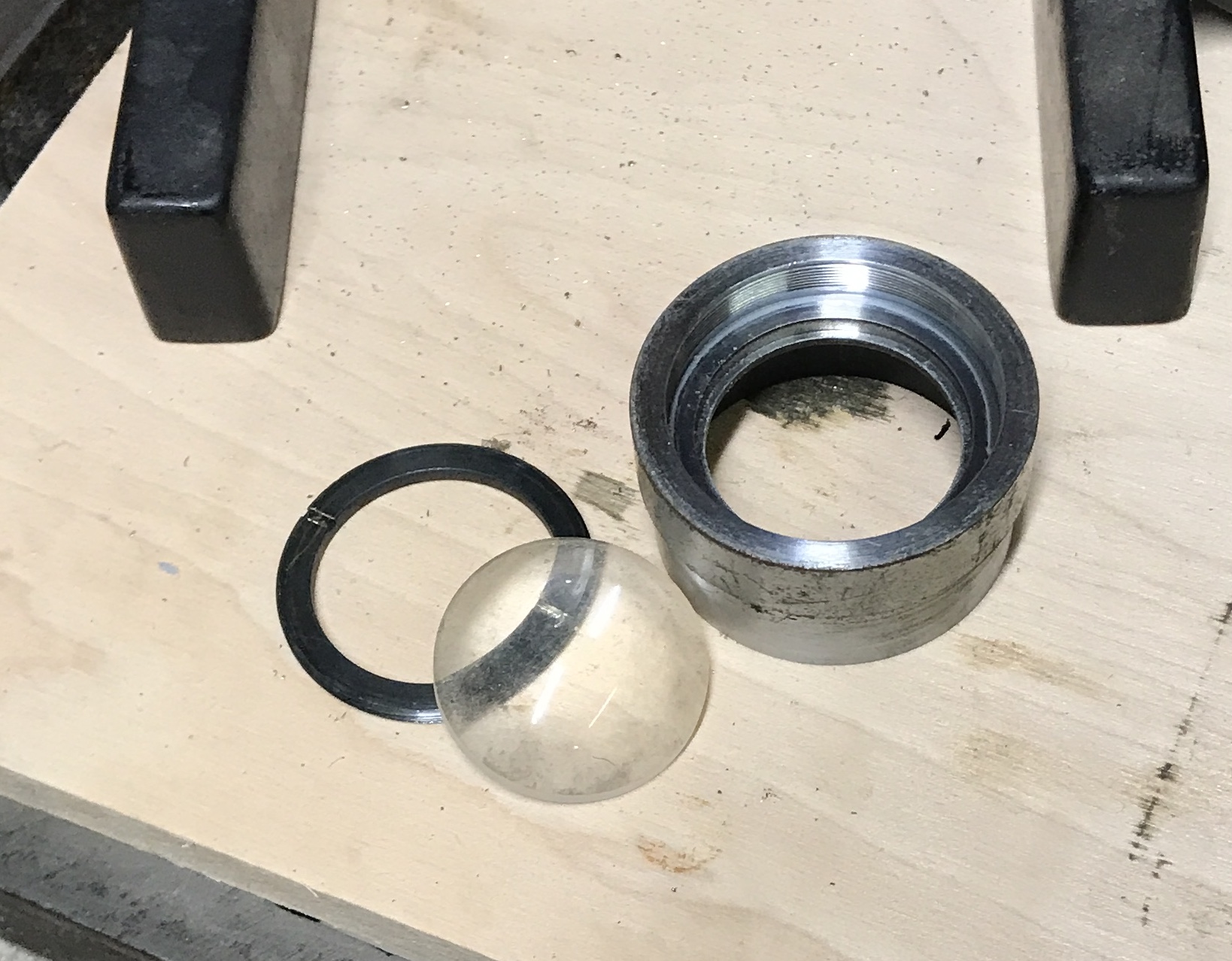
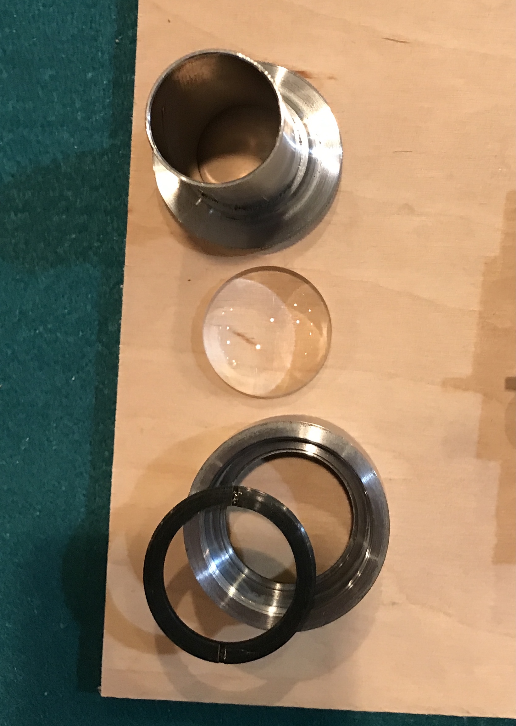
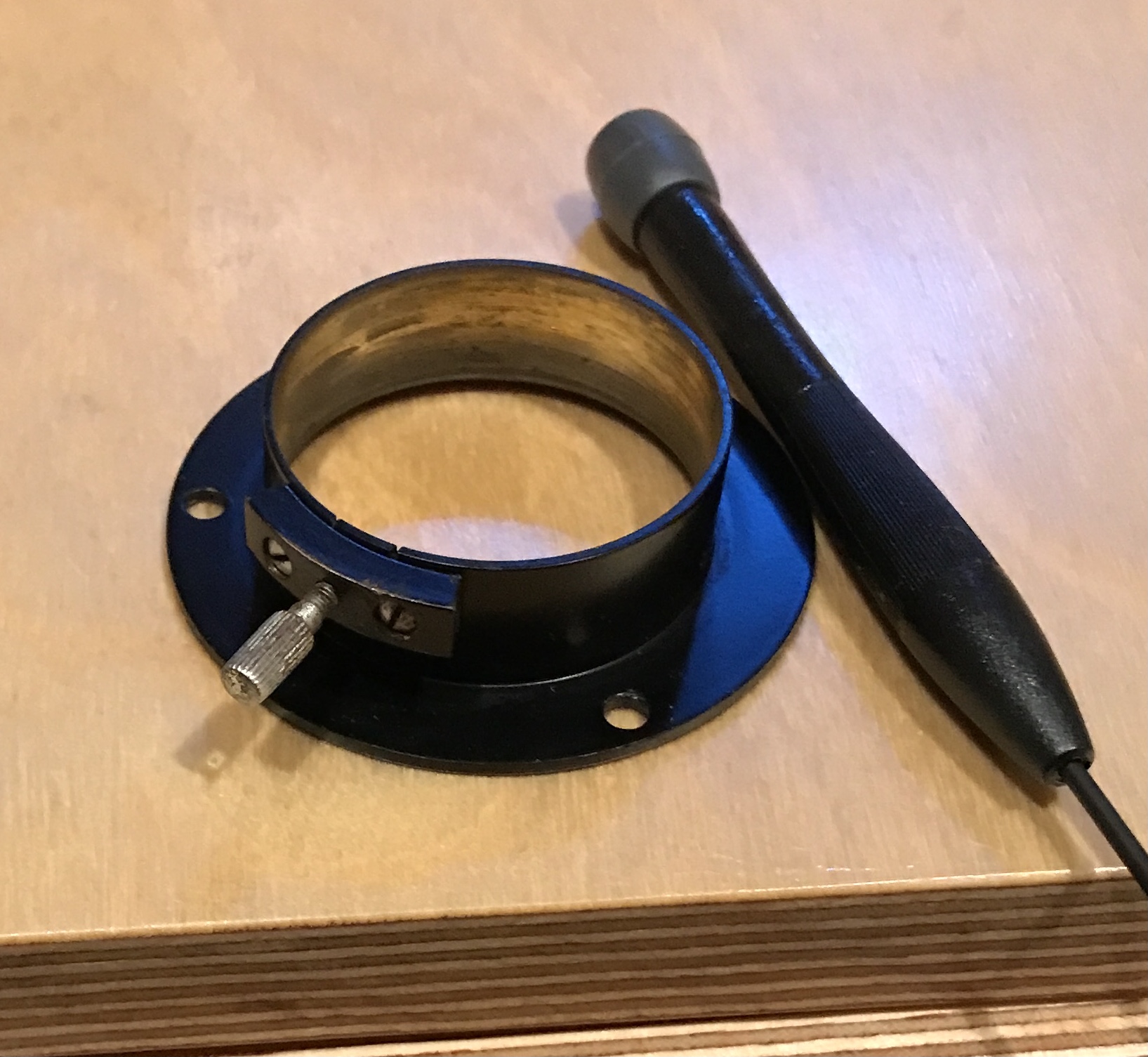
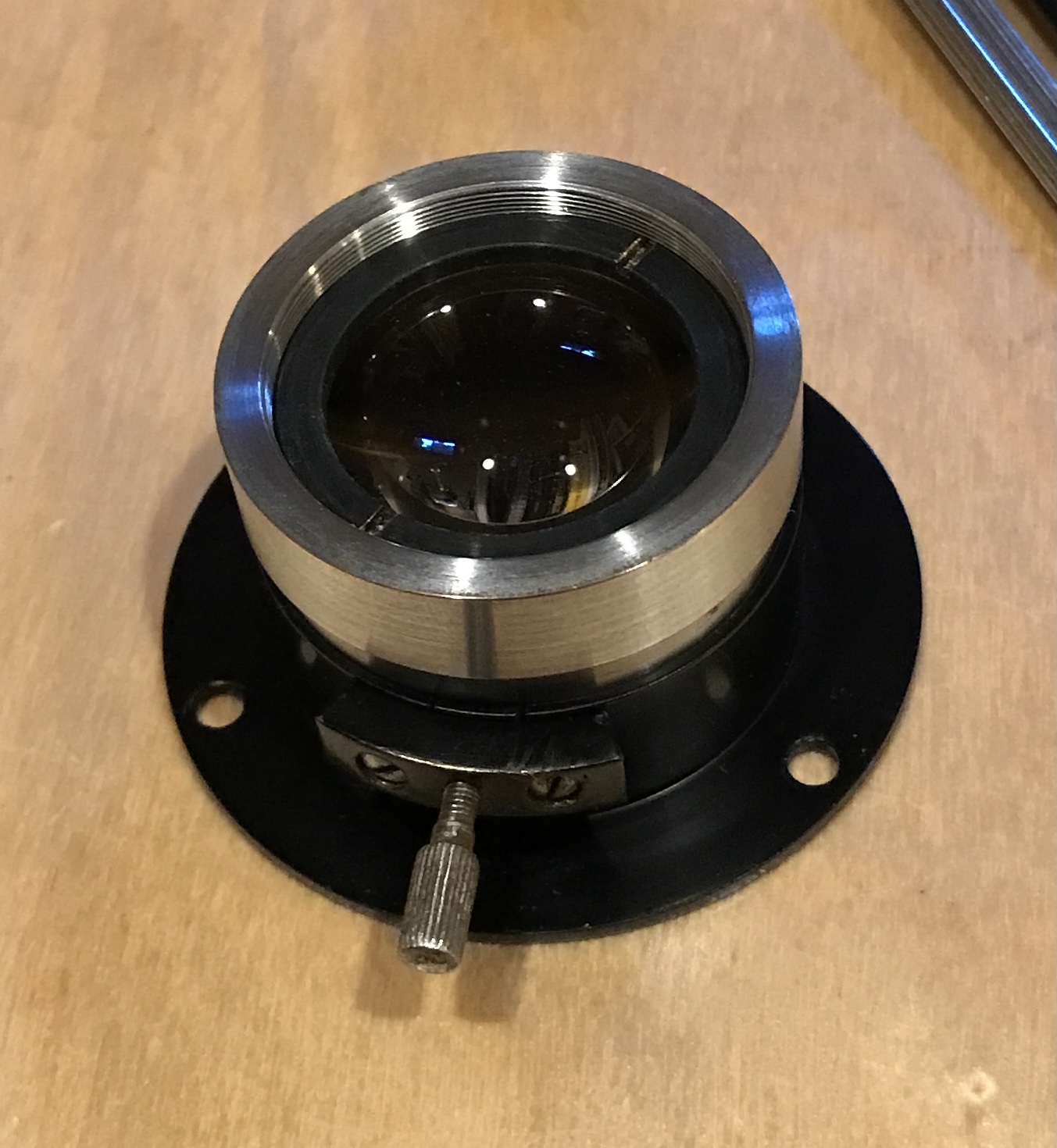
The light admitting assembly has a half round lens. This is held into the frame with a threaded ring. The ring has two "screwdriver" slots. The assembly was held in the vise and two small screwdrivers were used to unscrew this ring. The bulge in the lens points up through the retaining ring when assembled.
There is a simple sliding tube to adjust the light admitting lens. This tube has two screws holding the lock. One was difficult to remove, but yielded to a jeweler's screwdriver held in a pair of pliers, while holding the ring in the vise.
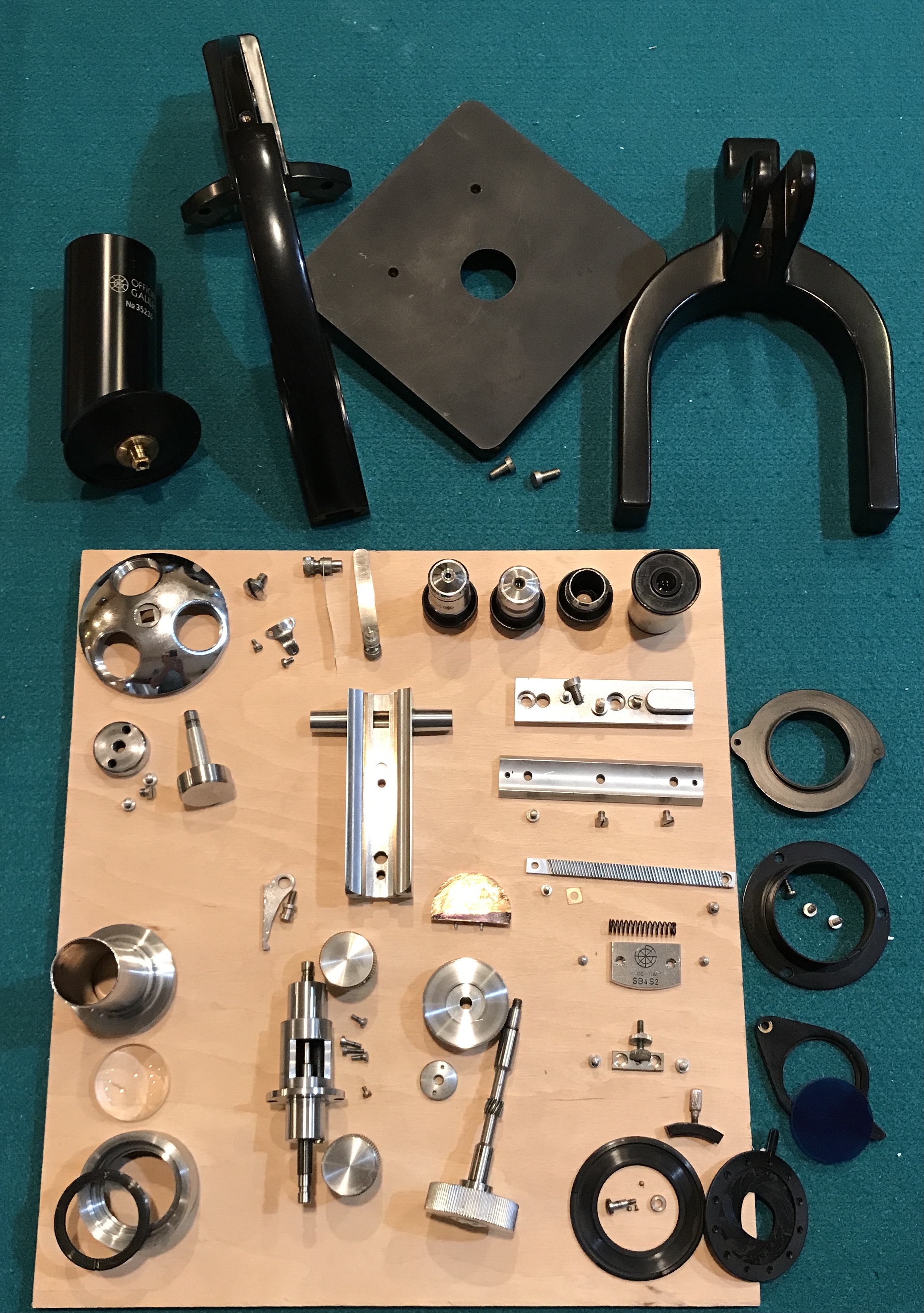
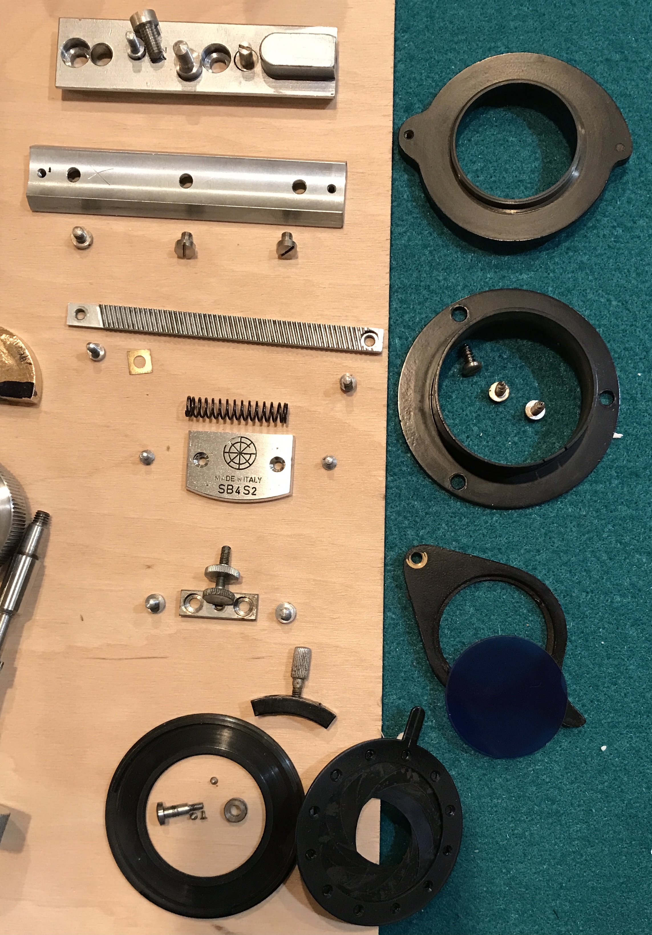
The final image of the disassembly is the sum total of parts. There are a few that will not be taken apart, due to the difficulties involved. With luck things are well enough documented here and the bag labels sufficiently clear that reassembly will go as smoothly as disassembly.
The glass was cleaned first. The lens in the light admission assembly was cleaned with Windex and a microfiber cloth. The other lenses were cleaned similarly. A q-tip also came in handy. The black parts from the light admission assembly also cleaned up nicely with the Windex. The blue filter glass was cleaned. It has a shiny side and a matte side. A screw was cleaned on the Scotch wheel. Rust was removed from a pivot with sandpaper.
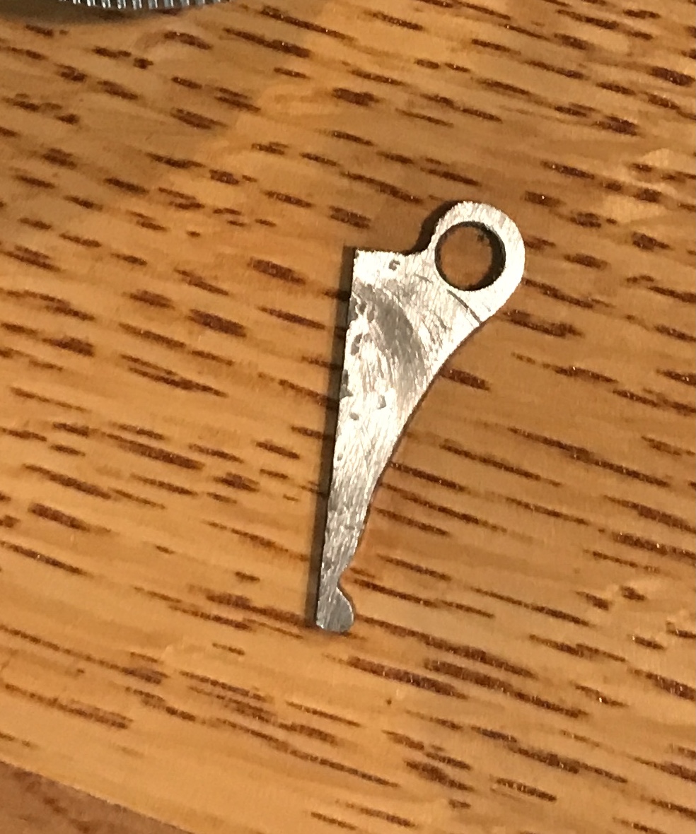
The pawl from the fine focus was measured. The steel is 0.103" thick. It varies from 0.455" to 0.080" wide. It is 1.041" long. The bearing that sits inside the pawl's hole is 0.182" in diameter. In the first photo is is clear how thin the steel was where it broke. The second view shows the slight bend in the pawl. I do not believe this was on purpose. The bump on the end is 0.127" long and 0.095" high. The area containing the hole is 0.235" wide and needs to be thicker. An estimate of the distance between the tip of the bump and the center of the hole is 1.02". A crude sketch is shown below.
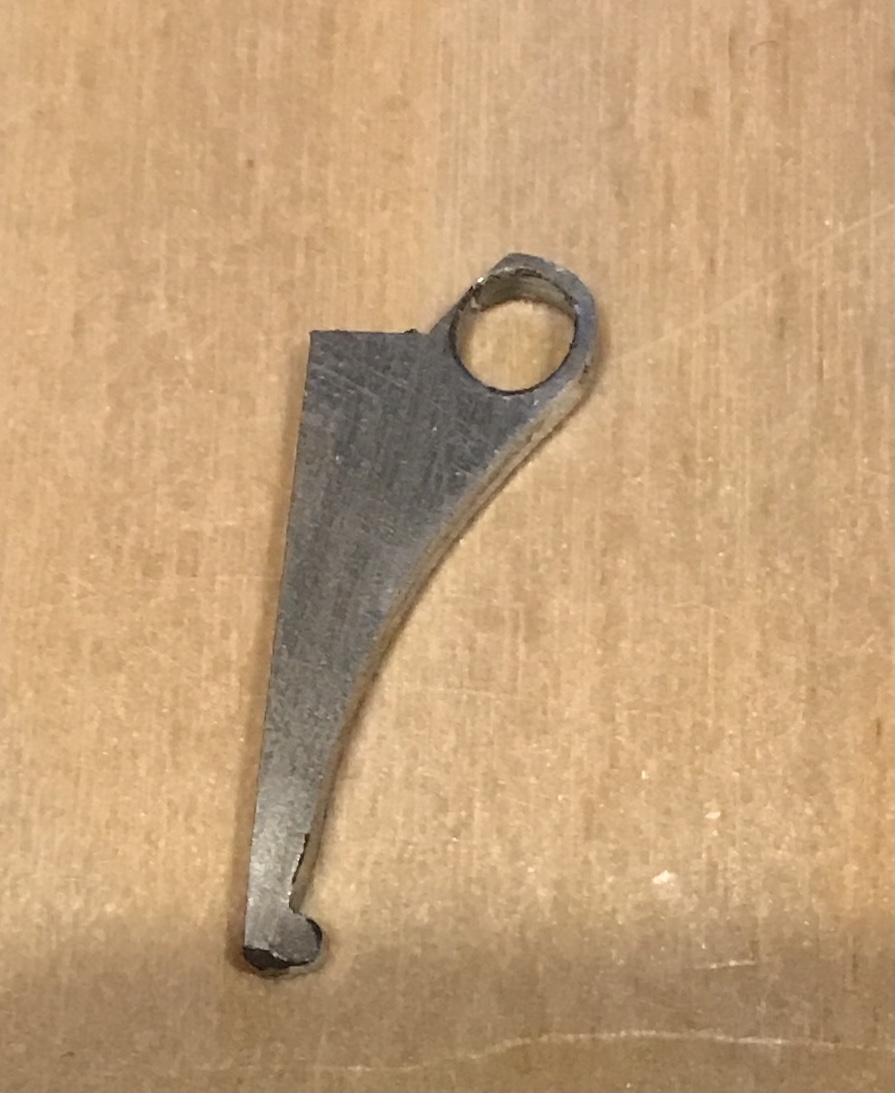
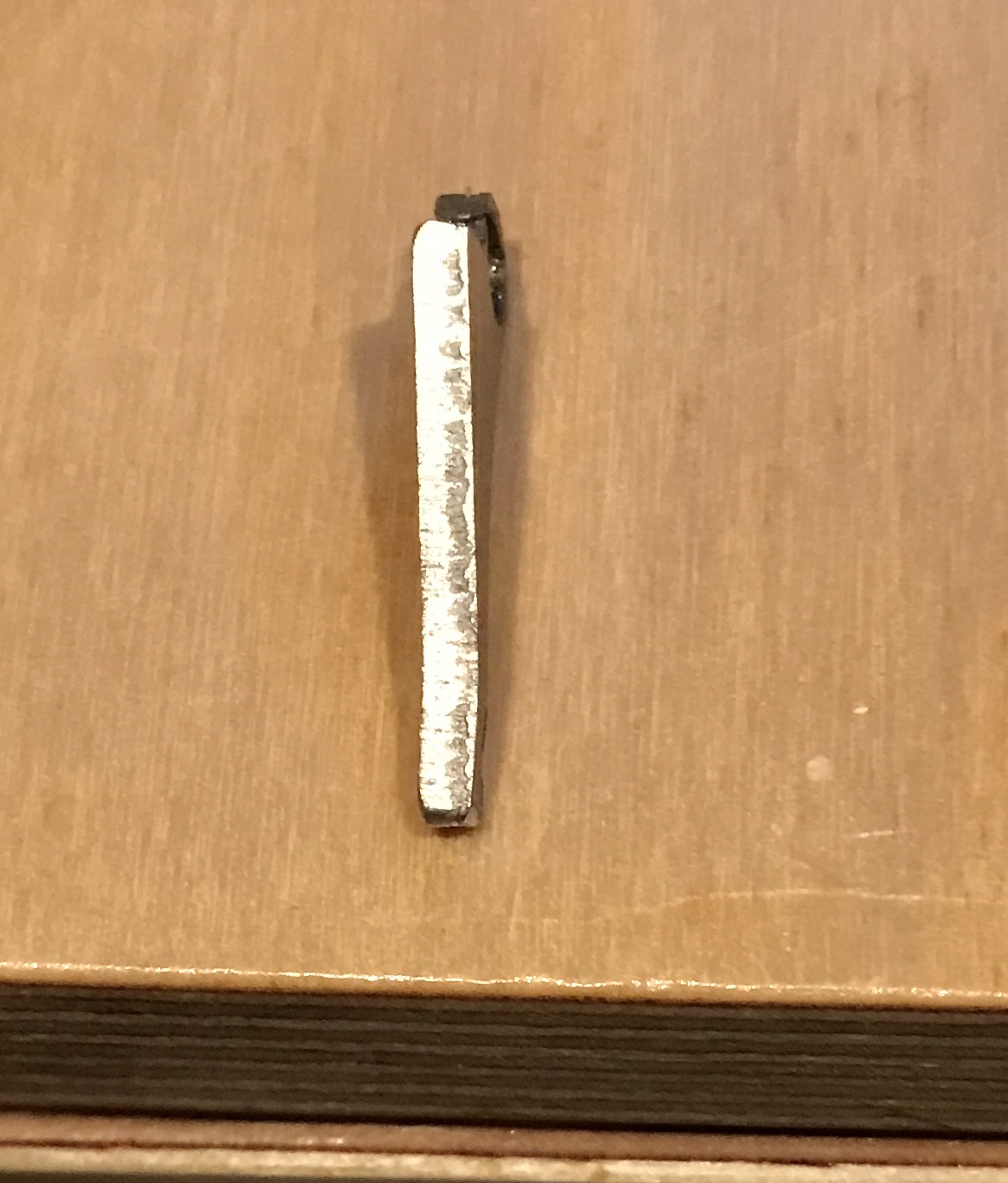
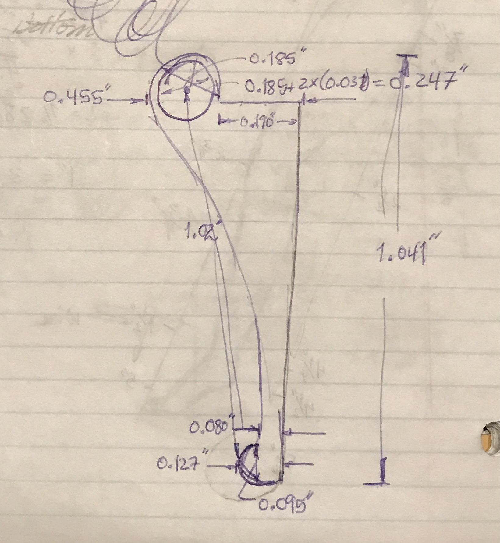
Note: the distance from the tip to the flat is 1.04". The distance to the top of the loop is 1.17".
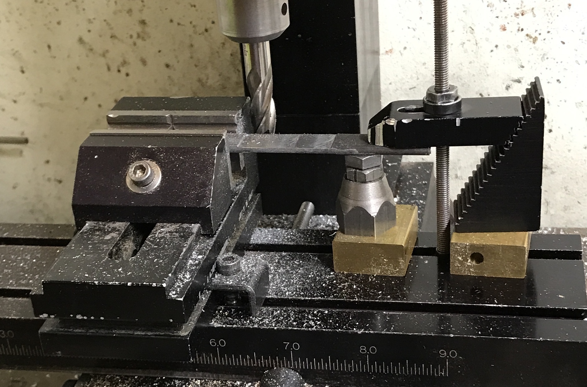
Making such a small part on the mill presents numerous holding challenges. Consequently, the part will be cut out of the middle of a 4" length of steel. This provides holding on both ends with straight edges. To this end a 4" length of 1/8" X 1/2" hot rolled steel was cut off with a hacksaw. It was held in the vise on one end and between a jack and a strap clamp on the other. One side was cleaned up with the two flute cutter and the other side was cut in 0.005" passes reducing the thickness to 0.103" over 1 1/4". One edge was also milled clean. The photo below shows the latter operation.
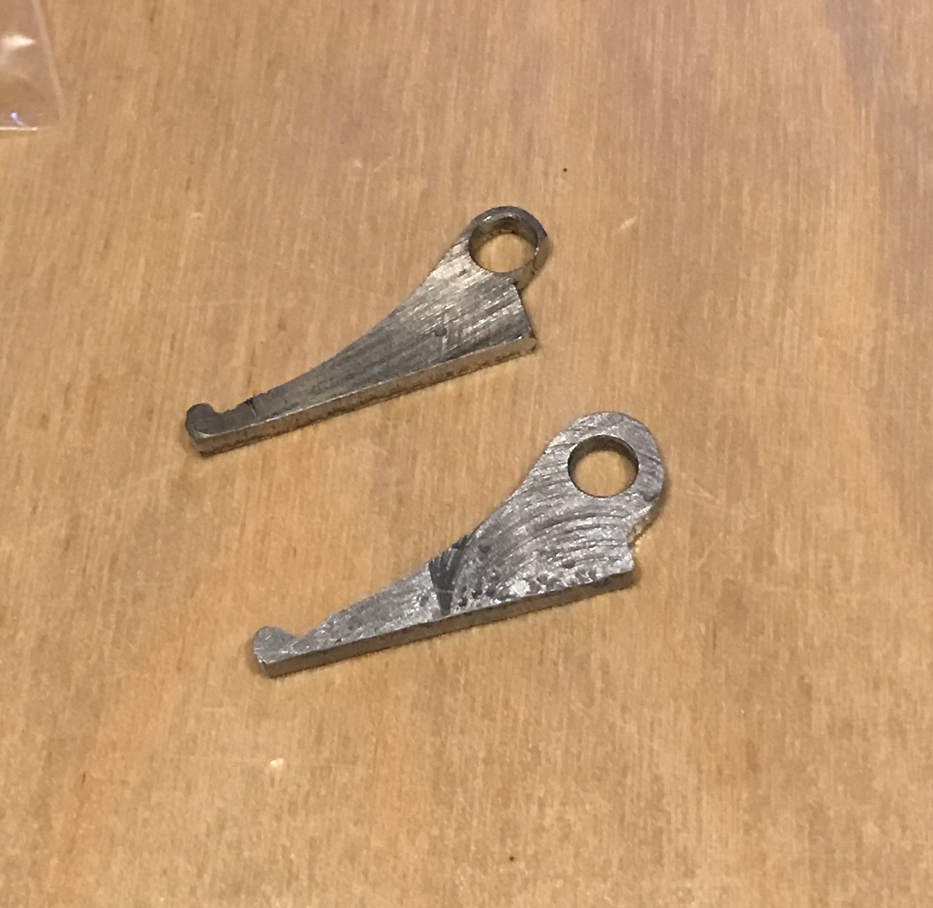
With this completed the shape of the pawl was laid out on the milled area of the steel. The center of the hole was transferred, center drilled and drilled with a #13 drill. The bearing spins smoothly in this hole. The steel at the short end was cut off with a hacksaw. Then the angled cut was made by hacksaw. Finally the other waste end was removed. The part was filed to shape with a variety of files. The photo below shows the finished pawl below the broken pawl. The new pawl was purposely left a lot beefier around the hole.
A few of the rustier parts were selected to try out the Naval Jelly purchased yesterday. These included the pivot screw and nut along with the lens selector and associated screws from both. The rust remover was smeared on with the gloves being worn. It was allowed to sit for ten minutes, the longest time recommended. The pink jelly was washed off with cold water. There was some improvement, but not much. All of these parts were placed in a jar of Evaporust, also purchased yesterday.
Naval Jelly is mostly phosphoric acid with small amounts of isopropanol and sulfuric acid. The non-aqueous ingredients in Evaporust are trade secrets.
The larger parts were just dirty. They were washed with soap and water. After drying they looked brand new. These parts are all made of brass except the slide platform. It may be made of hard rubber. The photo shows how well they all cleaned up.
I would like to know the source of the black paint used on these parts. It has lasted for many years without scratching or marring. It may be japanning, a hard black varnish containing asphalt.
Eventually all of the parts were cleaned up via a combination of Evaporust and sanding, sometimes up to 2000 grit. The first photo below shows all of the cleaned and shiny parts. The remainder show the same, but with close-ups of certain subassemblies.
The assembly will proceed mostly in reverse order of the disassembly. The light subassembly tube was held in the vise and given a bit of squeeze in order to attach the clamp screw. The light admitting lens was placed in the slide holder and the two slotted retaining ring was screwed into place holding it tight. The lens assembly slid easily into the tube with a twisting motion.
Assembling the viewing tube and its associated parts was next. The small selector was screwed into position with two screws. Three screws affixed the dovetail.
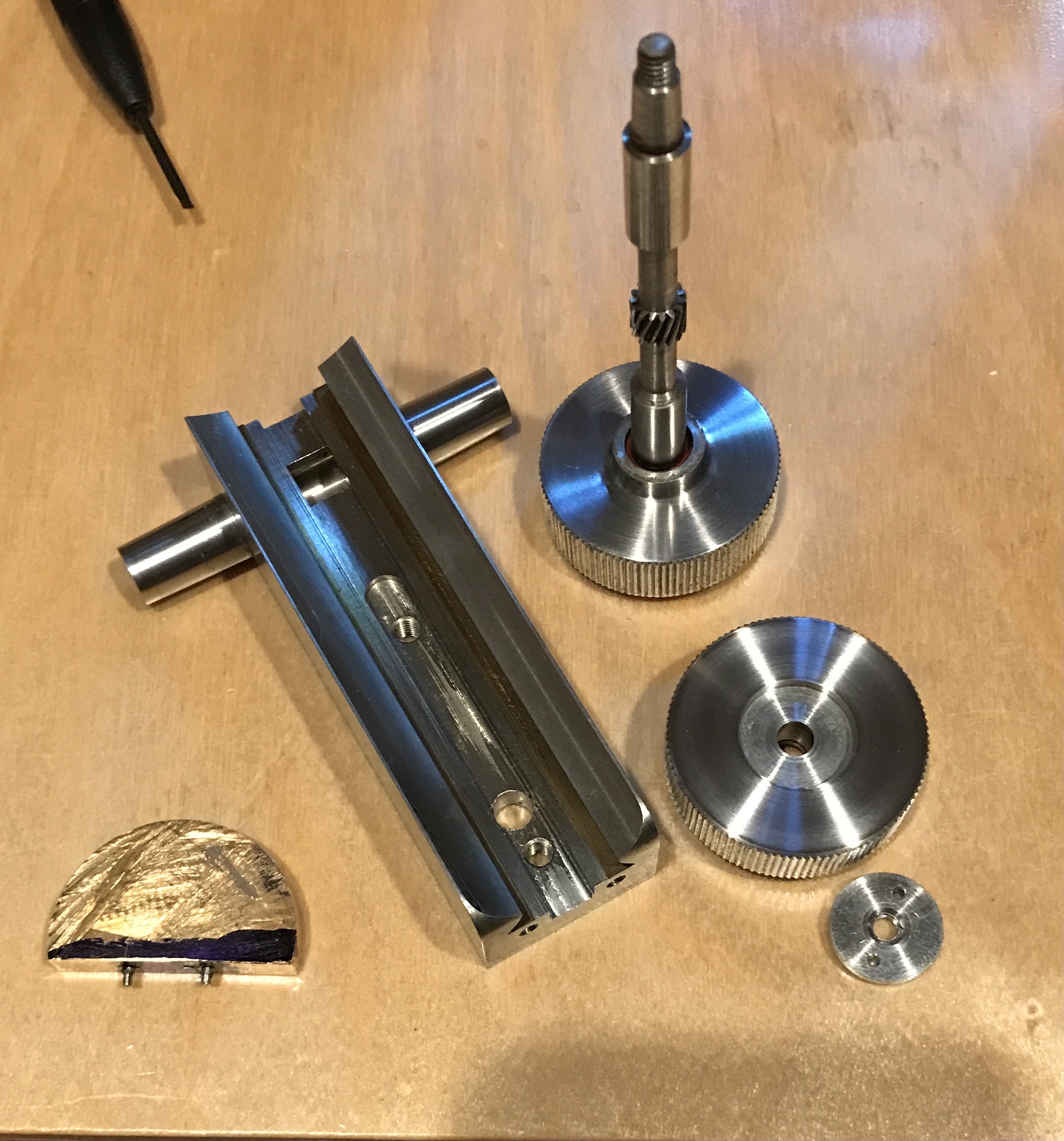
The coarse adjust mechanism was put together. White lithium grease purchased for the South Bend lathe spindle cone was put inside the bearings and on the gear. The knob/shaft was pushed through and the opposite knob slid onto the shaft. The pin screw was tightened to hold everything together.
The next step is mounting this coarse adjustment mechanism on the image tube dovetail. The rack is mounted between the two parts. I lost one of the thin square spacers. I hope to get by without using them. The spacer I have is 0.005" thick. My lucky day! I walked into the wood shop and immediately spotted the missing spacer lying on the floor!
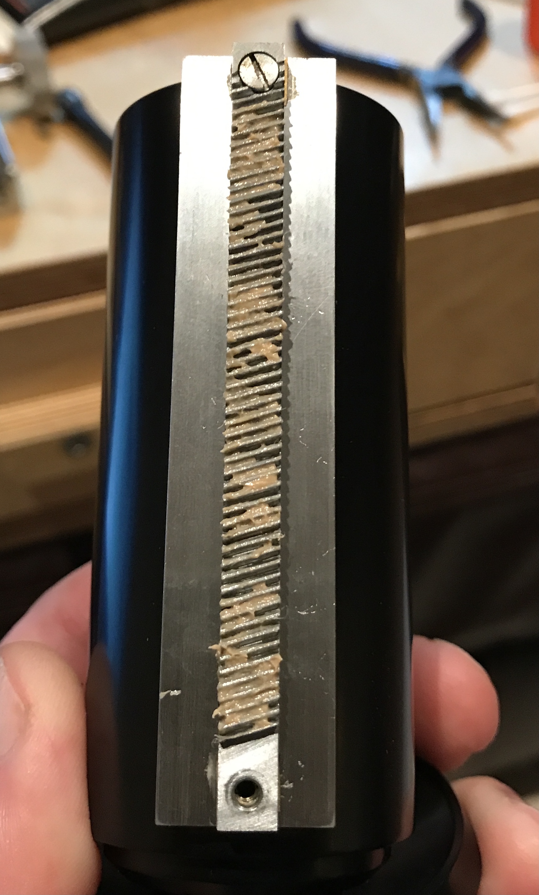
A spot of grease was placed around each of the two screw holes in the viewing tube dovetail. A thin brass spacer was placed over each hole. The rack was screwed into place with only the top screw. This is the thinner headed screw in the deeply countersunk hole. Grease was smeared over the length of the rack as shown below. The adjusting mechanism's dovetail was oiled with 3-in-1 oil and slid up from the bottom of the viewing tube to install. The rack's second screw was installed through the provided hole in the adjusting mechanism. The assembly at this stage is shown in the second photo below.
The bottom plate and its stop screw were installed. The screws were oiled prior to installation.
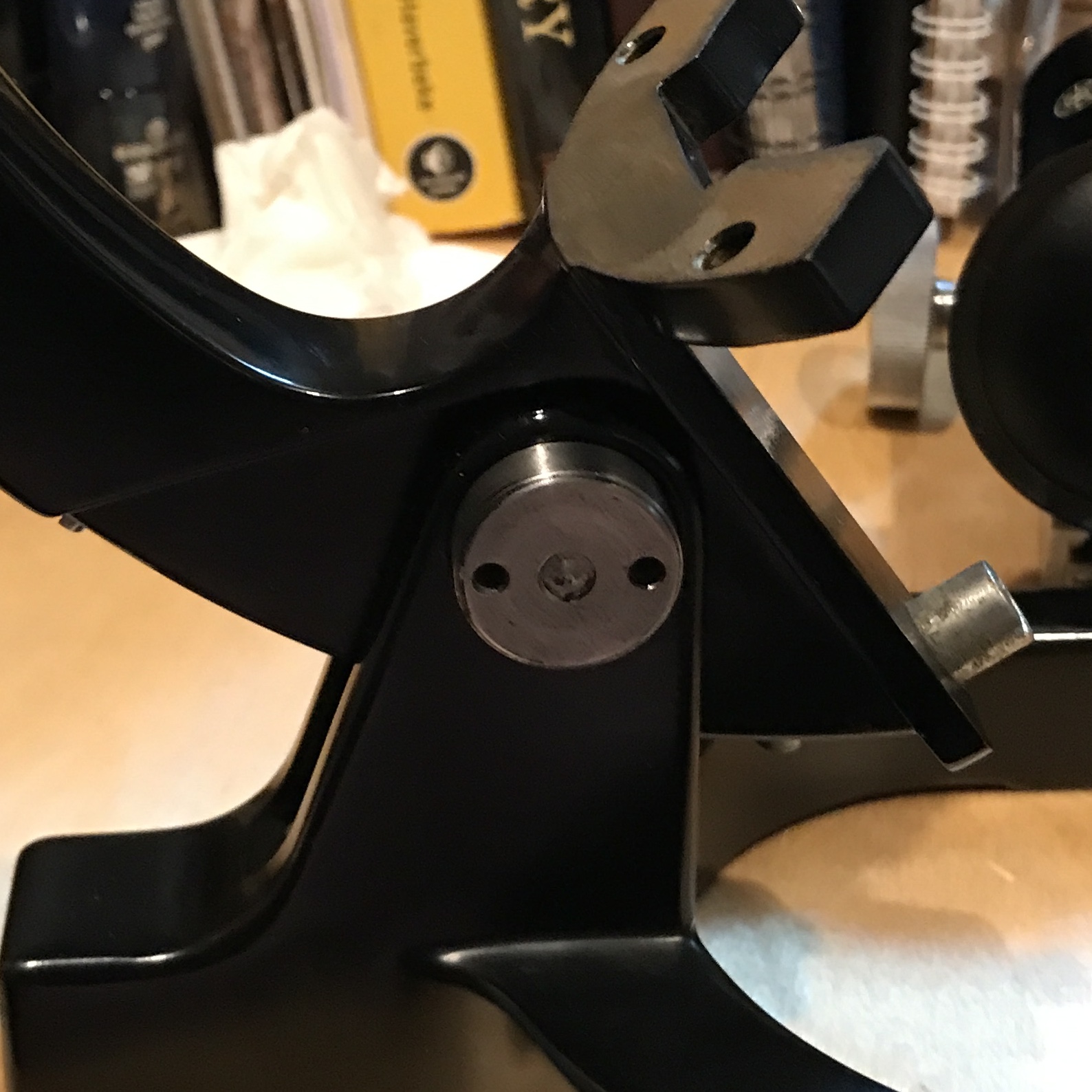
The frame was assembled with the pivot screw. First, the four screws on the two frame members were installed (probably for accessories). The steel bearing was oiled on its ends and the upper frame was forced into the lower. The oiled pivot screw was installed with its pin aligned with the provided hole. The pivot pin required a few taps with a rubber mallet to seat. The two pin nut was installed on the opposite end of the pivot screw.
The fine adjust mechanism was installed next. After doing it the wrong way I realized the longer set of two screws serve as set screws in the knobs, while the shorter screwed the flange to the frame. Oil was applied to the internal screw and to the individual screws. A small amount of grease was applied to the wheel. The flange side knob was installed first, followed by the numbered knob on the opposite side.
The pawl was the next installation challenge for my large clumsy fingers. Once I determined the correct way to install it. the back side was greased as was the bearing. I was unable to completely screw in the screw. The part around the bearing is a little too beefy.
The pawl was removed and filed to a slightly smaller size. It was also thinned a bit. After regreasing it was reinstalled. It is not a loose fit, but moves smoothly when the knobs are turned. The next dovetail was attached to the viewing tube with two screws. I was struggling to figure out how the fine focus works. The pin sticking out on this last dovetail rides on the small flat at the top of the pawl. When I installed the viewing tube on the frame by sliding it down it comes to a hard stop. This should be the pin resting on the pawl's flat. I am having a hard time determining whether that is the case or if the pin is stopping short because the pawl is larger on that side.
Using the Brown & Sharpe height gauge I was unable to measure any displacement upon turning the fine focus knob three or four full turns. I think this implies more pawl filing is required to thin the area near the flat. This was the area in the original pawl that was so thin it broke.
A few measurements later and the problem was revealed in all its ugly glory. The edge of the screw holding the pawl in place is 0.073" from the center of the dovetail. The pin is centered in the dovetail and is 0.142" in diameter. There is 0.002" to spare for the pawl in that spot. They drilled the hole in the wrong place!
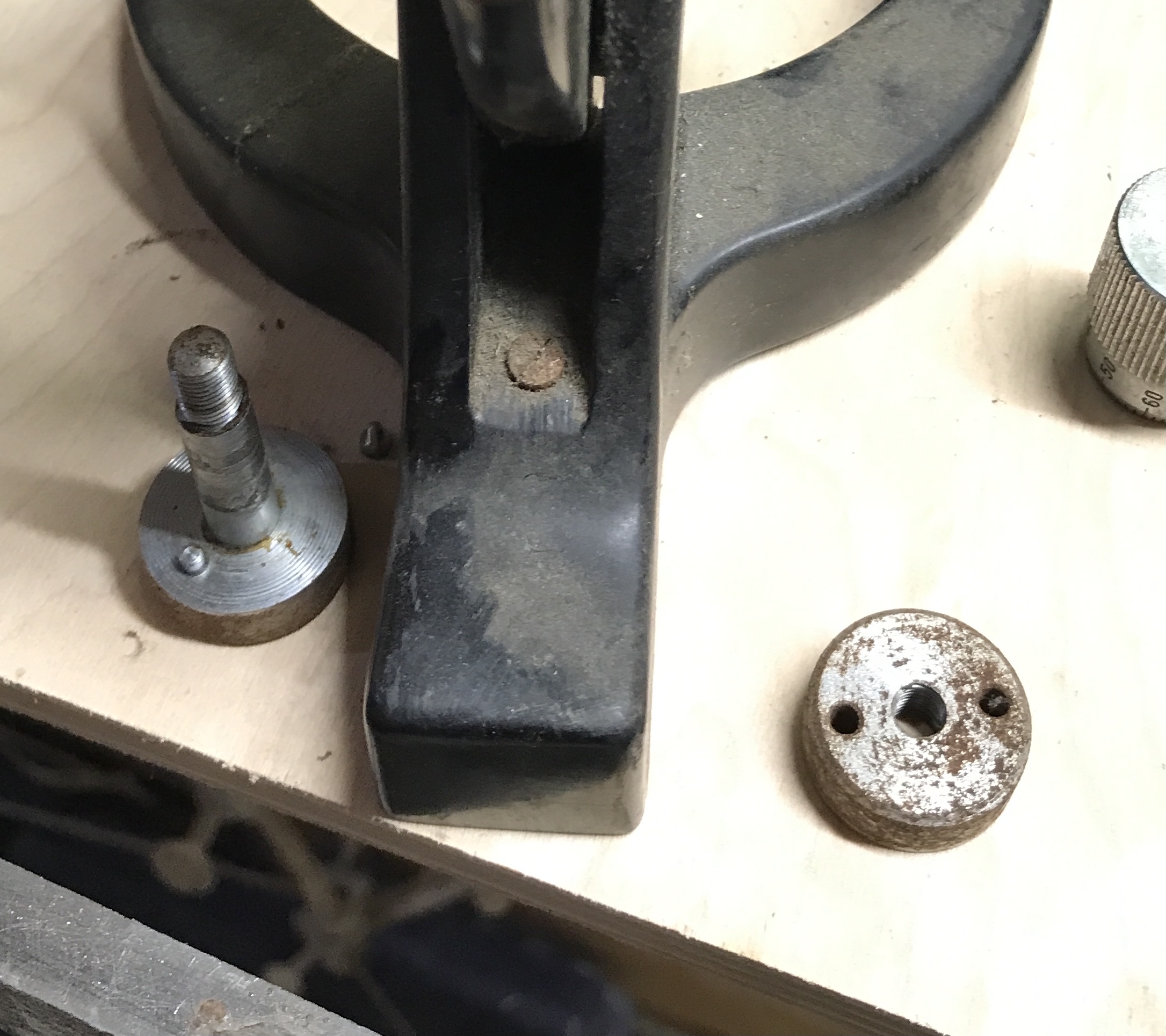
I don't want to plug the hole and redrill it. That would be too difficult to get an accurate location. The other option is to remove the pin and turn it down to a narrower size or make a new one. The pin was removed and is shown below.
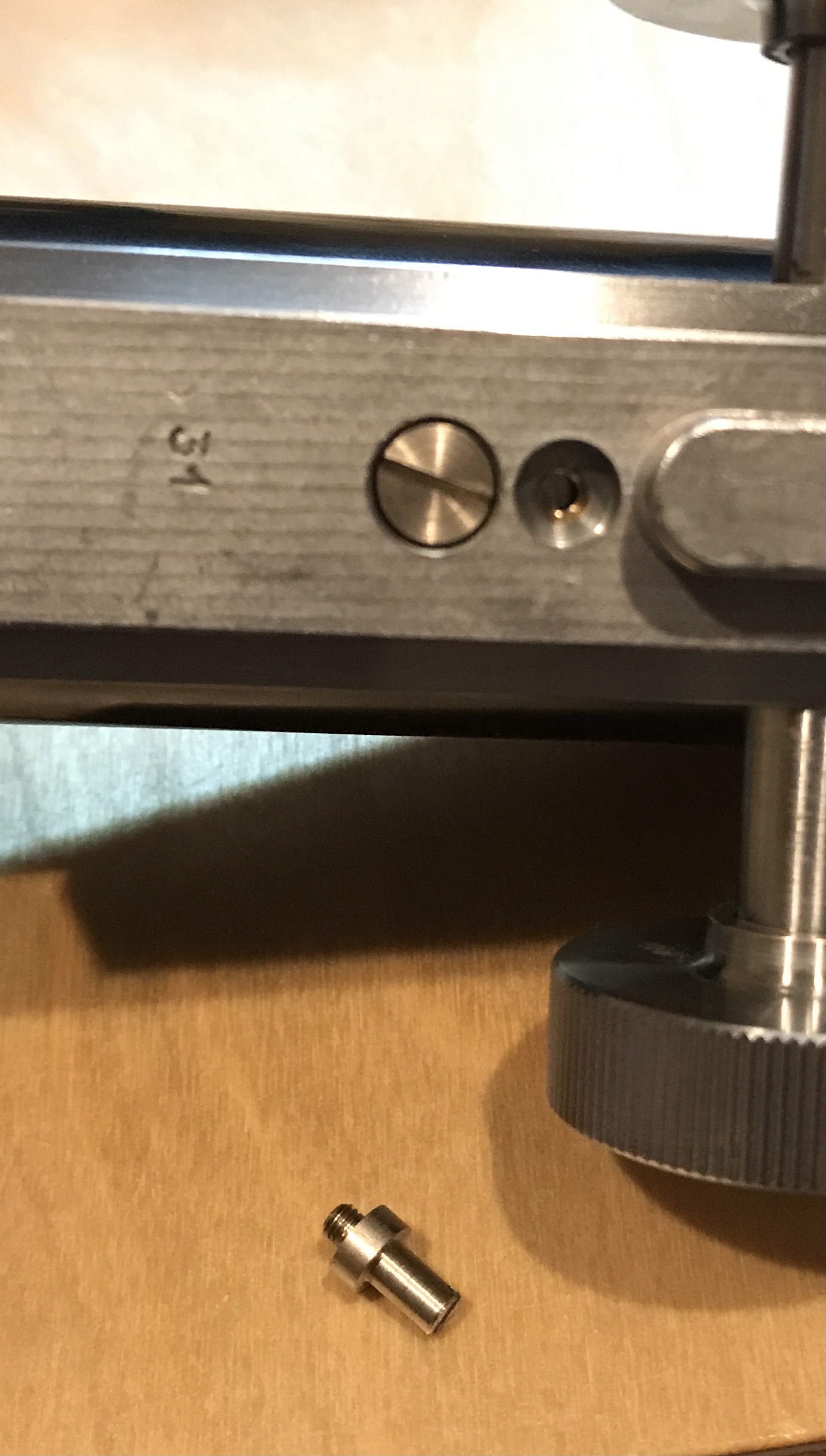
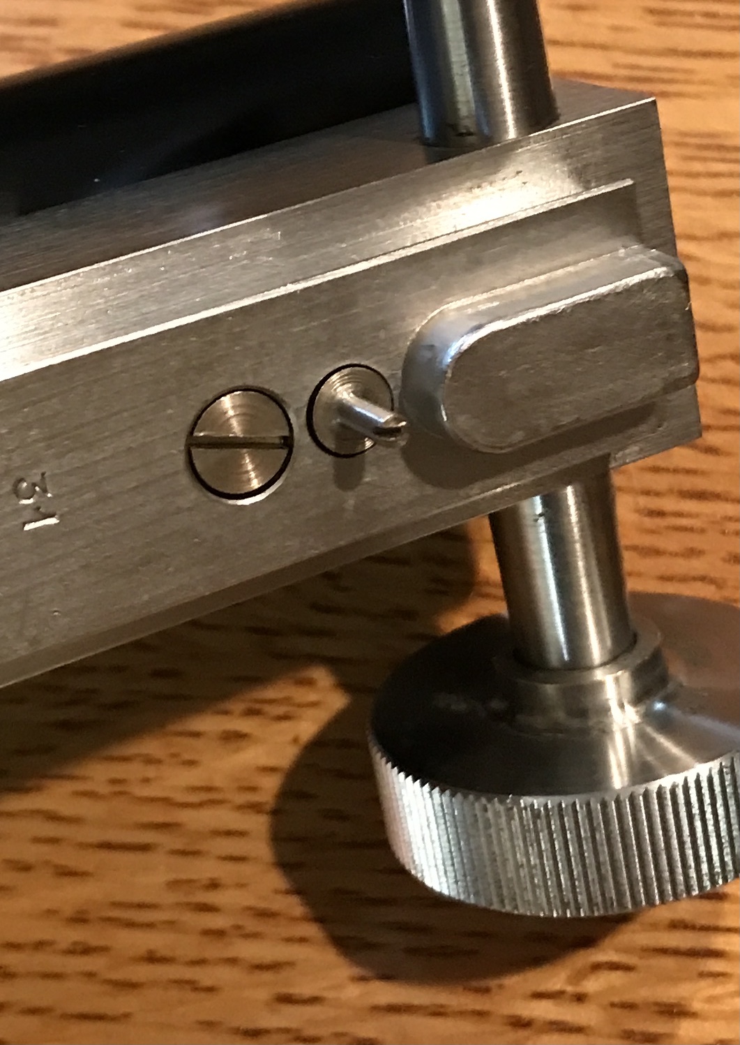
The pin was held in the three jaw chuck and reduced to 0.092". It is shown installed below. The pawl was removed again and filed until the thickness in the offending region is 0.032". It is also shown below after filing and after installation. After installing the pawl the viewing tube was installed. The fine focus knobs moved the tube as expected. The top plate was screwed into place (the second time with the spring).
The alien lens selector was installed. The lenses were screwed into place. Both steps are seen below.
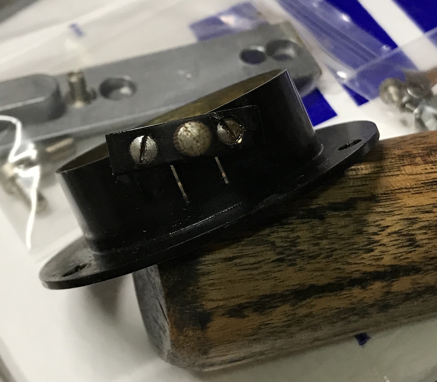
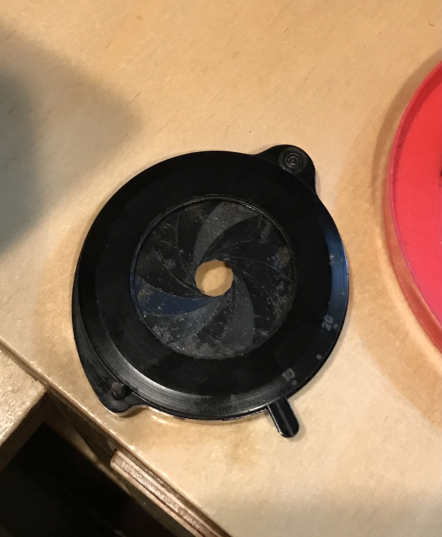
The light assembly was nearly the last item. The first and most challenging task was putting the diaphragm together. It uses three of the tiniest screws I have ever seen. (Two can barely be seen in the first of three photos below.) The first time I assembled the three parts, the diaphragm was open, but turned to the wrong end of the slot that constrains the lever. It was opened back up and the diaphragm rotated. After reassembly the diaphragm opened, but it was not a round opening. I took the assembly apart again. I played with the 'fins'. They were pretty tight, probably because of the corrosion I did not know how to remove. I put a bit of oil on them and the movement became much easier. I also aligned the fins. It was put together for a third time (a screw was lost and found) successfully. This took over an hour. I hate tiny screws!
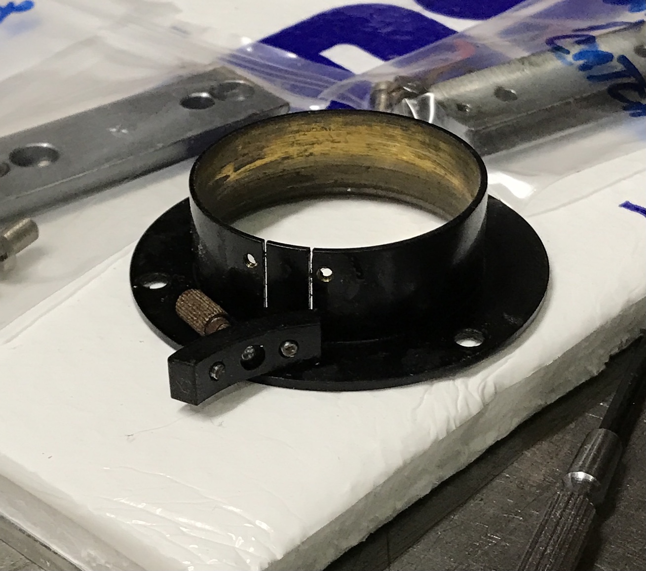
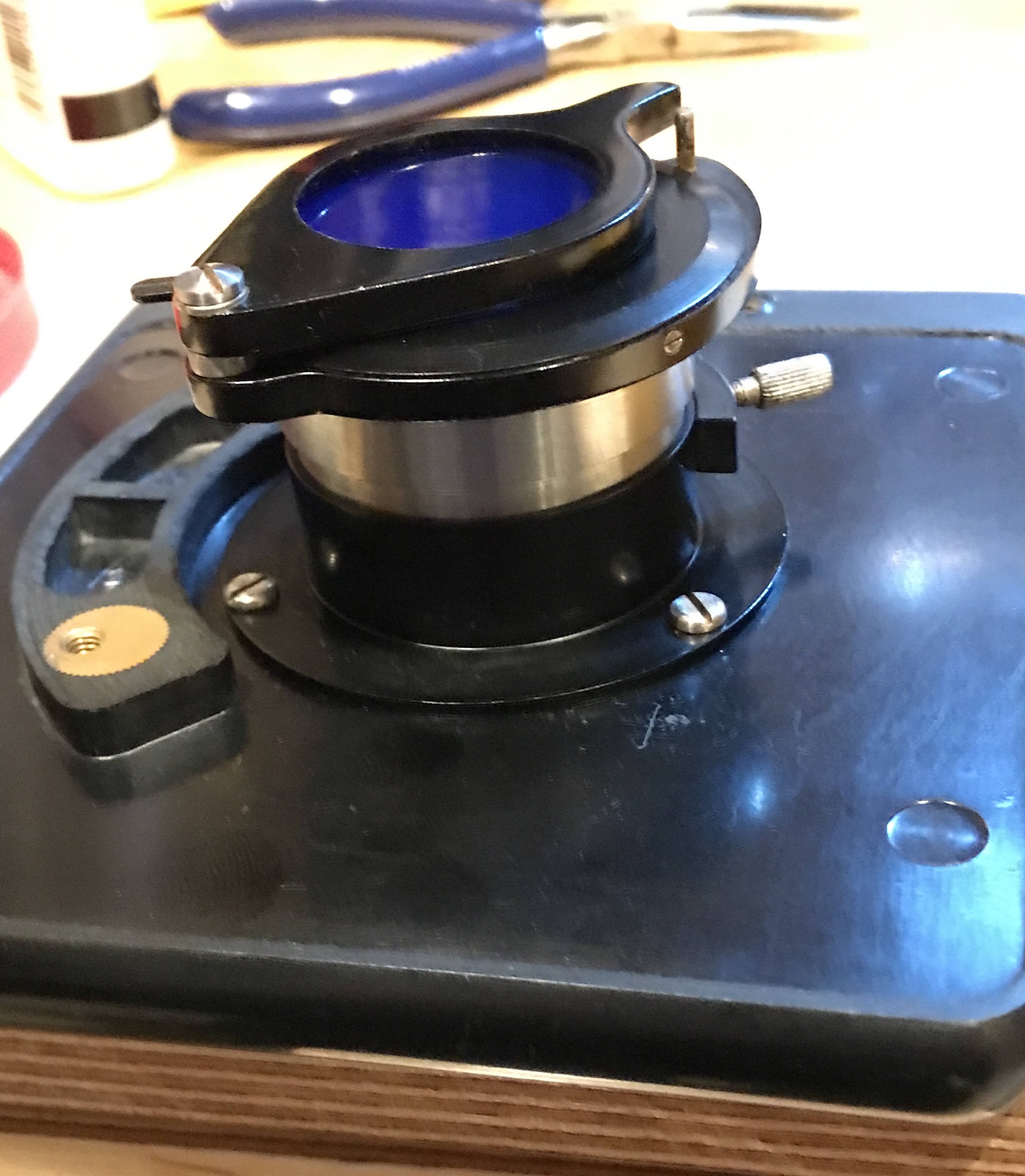
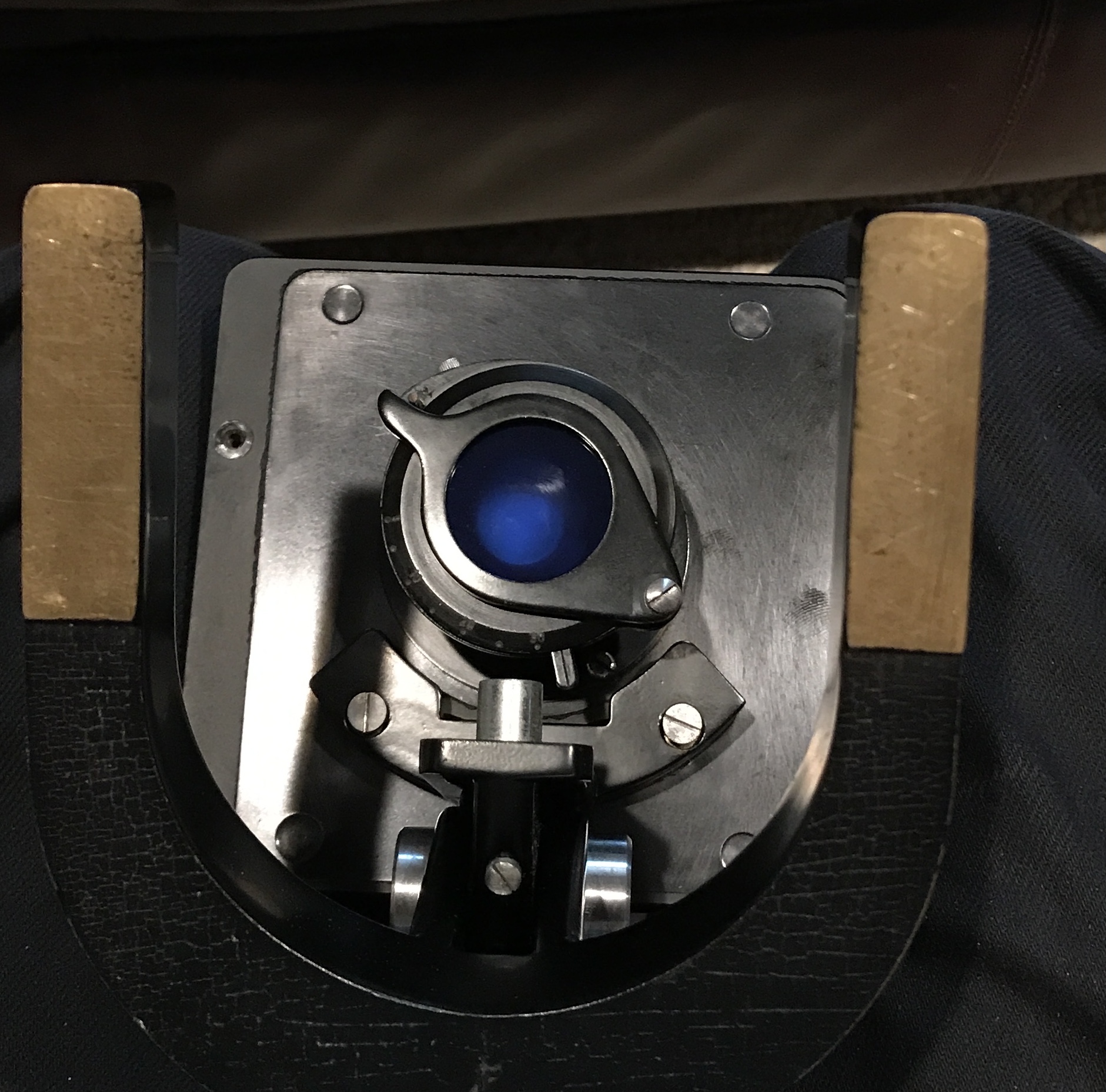
A long screw with a washer and a bearing went through the filter holder and into the diaphragm assembly. The diaphragm assembly was screwed to the light admitting lens tube. The inside of the sliding tube was oiled and the lens tube slid into place. Three screws held this assembly to the underside of the specimen table. The table was screwed to the frame with two screws. Two shots of the assembled light admitter are shown below.
The two specimen clips were inserted into the table. The eyepiece tube was screwed to the top of the viewing tube. The 10X lens was slid into the eyepiece tube. The microscope is ready for use, at least once I purchase a light source.